27Installation and maintenance manual ecoTEC
4.13.4 Connection of programmable thermostats
LN
234
LN 3
4
1
ACL Drayton
Lyfestyle PT271, PT371
ACL Drayton
Digistat 2, 3, 4
ACL Drayton
Digistat RF - SCR Receiver
Danfoss Randall
TP4, TP5, TP5E
Danfoss Randall
TP5E RF with receiver RX1
Danfoss Randall
TP75
Grässlin Towerchron
RTC7
Honeywell
CM61, CM67, CM31, CM37
Horstmann
Centaurstat 1, 7
Landis & Staefa
REV 11, REV 15, REV 22
12
34
3
Sunvic
TLX 6501
Sunvic
TLX RFP, TLX RFD
Vaillant
VRT 230, 220
N1
3
N3
2
L
L
4
32
43
1
LN
234
LN 3
4
1
BC
2341
A
3
56
4
12
34
3
AB
34
C
12
4
34
3
LL1
34
Smiths Timeguard
ProgramaSTAT PRT11, PRT17
LN
4
LN
3
34
12
34
3
LN
234
LN 3
4
1
34
34
5
5
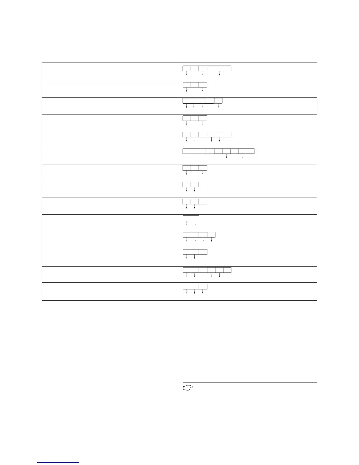
Fig. 4.18 Connection details for programmable thermostats
4.14 Controls (800 series)
4.14.1 External electrical controls
The boiler terminals 3, 4 and 5 are for connecting exter-
nal electrical controls such as a time switch and/or room
thermostat. Terminals 3 and 4 are linked together when
the boiler is supplied. If external controls are used, this
link must be removed, and the controls connected
across terminals 3 and 4. Terminal 5 is an additional
neutral connection for external neutrals such as from
the anticipator of a room thermostat.
4.14.2 Connection of external controls
4.14.3 Connection details for programmable room
thermostats
Fig. 4.18 shows the connection details where a program-
mable room thermostat (time switch with build in room
thermostat) is used to control the boiler.
Note
The numbers with arrows indicate connection to
the relevant terminal in the boiler terminal
strip.
Boiler installation sequence 4
 Loading...