46 Installation and maintenance manual ecoTEC
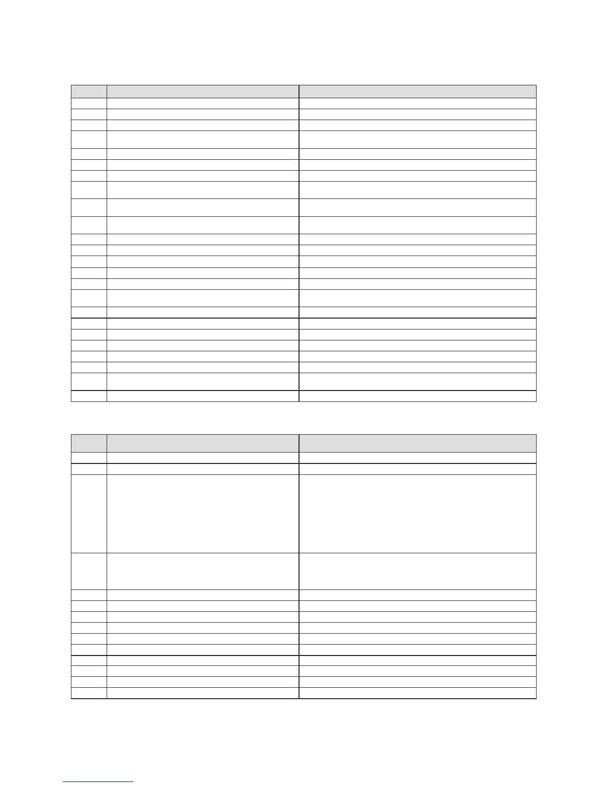
Display Meaning Display value/adjustable value
d.00 Heating partial load Adjustable heating partial load in kW (factory setting: max. output)
d.01 Water pump return water time for heating mode 1 - 60 min (factory setting: 5 min)
d.02 Max. blocking time heating at 20 °C Flow temperature 2 - 60 min (factory setting: 20 min)
d.03 Drinking water flow temperature reading (800 series
only)
in °C
d.04 Storage temperature reading (only 600 series) in °C
d.05 Flow temperature target value in °C, min. 30 °C and max. the value set in d.71
d.06 Drinking water temperature target value in °C, 35 to 65 °C
d.07 Warm start temperature target value (800 series only)
Storage temperaturetarget value (600 series only)
in °C, 40 to 65 °C
in °C, 15 °C for left stop, then 40 to 65 °C
d.08 Room thermostat at terminal 3-4 0 = Room thermostat open (no heat request)
1 = Room thermostat closed (heat request)
d.09 Flow target temperature from external analogue regula-
tor to terminal 7-8-9/eBus
in °C, minimum from ext. eBus target value and target value terminal 7
d.10 Status internal heating pump 1, 2 = on, 0 = off
d.11 Status external heating pump 1 to 100 = on, 0 = off
d.12 Status external storage charging pump 1 to 100 = on, 0 = off
d.13 Status external circulation pump 1 to 100 = on, 0 = off
d.22 Hot water request, Terminal C1/C2, impeller 1 = on, 0 = off
d.25 Storage charging/warm start through warm start clock
regulator/release timer
1 = yes, 0 = no
d.40 Flow temperature Actual value in °C
d.41 Return temperature Actual value in °C
d.47 Outside temperature (with connected VRC 410s) Actual value in °C (uncorrected value)
d.67 Remaining burner locking time in min
d.76 Appliance variant (device specific number) 00 to 99
d.90 Digital regulator status 1 = identified, 0 = unidentified (eBUS Address <=10)
d.91 DCF status with connected external probe with DCF77
receiver
0 = no reception, 1 = reception, 2 = synchronised, 3 = valid
d.97 Activation of the second diagnosis level Password: 17
Table 8.2 Diagnosis codes of the first diagnosis level
Display Meaning Display value/adjustable value
d.17 Heating flow/return regulation changeover 0 = flow, 1 = return (factory setting: 0)
d.18 Pump mode (return flow) 0 = return, 1 = nonstop, 2 = intermittent, 3 = winter
d.19 Only in ecoTEC plus:
Operating modes of the two-stage heating pump
0 = Flow 300 msec Stage 2, then stage 1, drinking water/storage
charging Stage 2, heating stage 2, return stage 1
1 = Flow 300 msec Stage 2, then stage 1, drinking water/storage
charging Stage 2, heating stage 1, return stage 1
2 = Flow 300 msec Stage 2, then stage 1, drinking water/storage
charging Stage 2, heating in dependence on d.00, return stage 1
(factory setting)
3 = Flow Stage 2, drinking water/storage charging Stage 2, heating
stage 2, return stage 2
d.26 Changeover option relay to BMU 1 = circulation pump
2 = ext. pump
3 = Storage charging pump
4 = solar pump
d.27 Changeover accessory relay 1 -
d.28 Changeover accessory relay 2 -
d.30 Control signal for both gas valves 1 = on, 0 = off
d.33 Fan speed target value in rpm/10
d.34 Fan speed actual value in rpm/10
d.35 Position of priority reverse valve (only 800 series) 0 = Heating; 1 = Hot water; 2 = Centre position
d.44 Ionisation current
Actual value/100 in µA
d.50 Offset for minimum speed in rpm/10, adjustment range: 0 to 254 (Factory setting: 20)
d.51 Offset for maximum speed in rpm/10, adjustment range: -99 to -0 (Factory setting: -30)
d.60 Number of temperature limiting cut-offs Quantity
Table 8.3 Diagnosis codes of the second diagnosis level
8 Troubleshooting
 Loading...