*****INTERNAL*****30 R_D proof- 26.10.2022 / 09:15:46- VaillantGroup\DOC-agt\Brand\VIH_QW_190_6\ENG\OI-II_GB_0020291525
46 Installation and maintenance instructions 0020291525_04
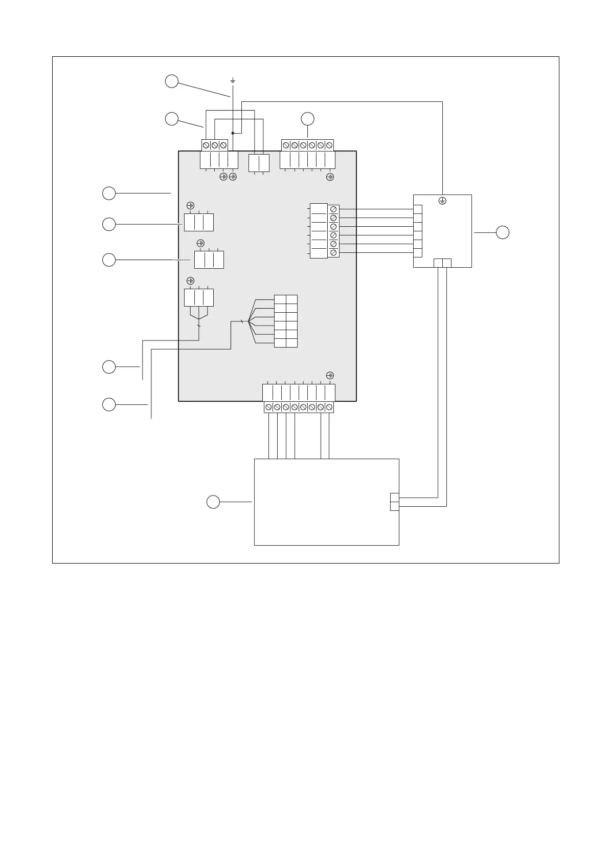
B Wiring diagram
1
2
3
4
5
6
L1
L1
L2
L3
N
3
2
1
L
N
3
2
1
L
N
X302
X300
X310
X311
X312
X314
X313
3
2
1
L
N
3
2
1
L1
N
3
4
1
2
N
L
1
2
3
4
5
6
L2
L3
L1
L1S
L2S
L3S
L2
L3
L1
L1S
L2S
L3S
8
7
6
5
4
3
2
1
L3_6
L3_5
L2_4
L2_3
L1_2
L1_1
N
X301
X328
12
11
6
5
4
2
3
1
10
9
8
7
12
5
4
8
1
7
2
3
6
9
10
1 Power supply PCB
2 For single power supply: 230 V bridge between
X311 and X310; for dual power supply: Replace
the bridge at X311 with the 230 V connection
3 Permanently installed protective conductor connec-
tion to the housing
4 [X300] Power supply connection
5 [X302] Safety cut-out
6 [X301] Back-up heater
7 [X328] Data connection to the control PCB
8 [X313] Power supply for the control PCB or the op-
tional VR 70/VR 71 or the optional external current
anode
9 [X314] Power supply for the control PCB or the op-
tional VR 70/VR 71 or the optional external current
anode
10 [X312] Power supply for the control PCB or the op-
tional VR 70/VR 71 or the optional external current
anode