*****INTERNAL*****30 R_D proof- 26.10.2022 / 09:15:46- VaillantGroup\DOC-agt\Brand\VIH_QW_190_6\ENG\OI-II_GB_0020291525
50 Installation and maintenance instructions 0020291525_04
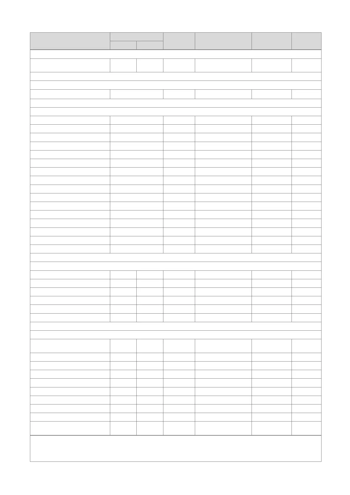
F Installer level overview
Setting level Values Unit Increment, select, ex-
planation
Factory setting Setting
Min. Max.
Installer level →
Enter code 00 99 1 (competent person
code 17)
17
Installer level → Fault list →
F.XX – F.XX
1)
Current value
Installer level → Test menu → Statistics →
Compressor hours Current value h
Compressor starts Current value
Build. pump hours Current value h
Build. pump starts Current value
4-port valve hours Current value h
4-port valve sw. ops Current value
Fan 1 operating hours Current value h
Fan 1 starts Current value
Fan 2 operating hours Current value h
Fan 2 starts Current value
EEV steps Current value
DHW PDV switch. ops Current value
Im. heater power cons. Current value kWh
Im. heater op. hours Current value h
Im. heater switch. ops Current value
No. switch. ops Current value
Installer level → Test menu → Check programmes →
P.04 Heating mode Select
P.06 Purge building circuit Select
P.11 Cooling mode Select
P.12 De-icing Select
P.27 Immersion heater Select
P.29 High pressure Select
Installer level → Test menu → Sensor/actuator test →
T.0.01 Building circuit pump
power
0 100 % 5, off 0
T.0.17 Fan 1 0 100 % 5 0
T.0.18 Fan 2 0 100 % 5 0
T.0.19 Condensate tray heater Off On On, Off Off
T.0.20 4-port valve Off On On, Off Off
T.0.21 Position: EEV 0 100 % 5 0
T.0.23 Heating coil compressor Off On On, Off Off
T.0.40 Flow temperature -40 90 ℃ 0.1
T.0.41 Return temperature -40 90 ℃ 0.1
T.0.42 Building circuit: Water
Pressure
0 3 bar 0.1
1)
See the overview of fault codes: Fault lists are only available, and can only be deleted, if faults have occurred.
2)
This parameter does not appear if a system control is connected.
3)
This parameter is only available in the products for Spain