*****INTERNAL*****30 R_D proof- 26.10.2022 / 09:15:46- VaillantGroup\DOC-agt\Brand\VIH_QW_190_6\ENG\OI-II_GB_0020291525
0020291525_04 Installation and maintenance instructions 15
Installation and maintenance
instructions
Contents
1 Safety .................................................................. 17
1.1 Intended use........................................................ 17
1.2 General safety information .................................. 17
1.3 Regulations (directives, laws, standards) ............ 18
2 Notes on the documentation ............................ 19
2.1 Further information .............................................. 19
3 Product description........................................... 19
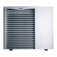
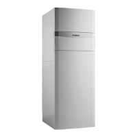
3.1 Heat pump system............................................... 19
3.2 Safety devices ..................................................... 19
3.3 Functional elements............................................. 20
3.4 Serial number ...................................................... 20
3.5 Information on the data plate............................... 20
3.6 Connection symbols ............................................ 20
3.7 CE marking.......................................................... 21
3.8 Benchmark........................................................... 21
3.9 Energy balance control........................................ 21
3.10 Compressor hysteresis........................................ 21
3.11 Cooling mode....................................................... 21
4 Set-up.................................................................. 21
4.1 Unpacking the product......................................... 21
4.2 Checking the scope of delivery............................ 22
4.3 Selecting the installation site ............................... 22
4.4 Permissible height difference between the
outdoor unit and the indoor unit........................... 22
4.5 Dimensions.......................................................... 23
4.6 Minimum clearances and installation
clearances ........................................................... 23
4.7 Product dimensions for the transport................... 23
4.8 Transporting the product ..................................... 23
4.9 Separating the product into two modules
where necessary.................................................. 24
4.10 Removing the casing ........................................... 25
4.11 Installing the casing ............................................. 26
4.12 Moving the electronics box (optional) .................. 27
4.13 Setting up the indoor unit..................................... 27
4.14 Removing the carrying straps.............................. 28
5 Hydraulics installation ...................................... 28
5.1 Carrying out the installation preparations ............ 28
5.2 Connecting the heat pump to the indoor unit....... 28
5.3 Connecting the building circuit............................. 28
5.4 Installing the domestic hot and cold water
connection ........................................................... 28
5.5 Installing potable water pipes .............................. 29
5.6 Hydraulic connection ........................................... 29
5.7 Installing the drain pipe on the expansion relief
valve .................................................................... 31
5.8 Connecting the condensate discharge ................ 32
5.9 Connecting additional components ..................... 32
6 Electrical installation......................................... 32
6.1 Preparing the electrical installation...................... 32
6.2 Requirements for the quality of the mains
voltage ................................................................. 32
6.3 Electrical partition ................................................ 32
6.4 Installing components for the energy supply
company lockout function .................................... 32
6.5 Removing the cover from the power supply
PCB ..................................................................... 33
6.6 Routing the cables in the product ........................ 33
6.7 Establishing the power supply, 1~/230V.............. 33
6.8 Establishing the power supply, 3~/400V.............. 34
6.9 Installing the system control in the electronics
box ....................................................................... 35
6.10 Requirements for the eBUS line .......................... 35
6.11 Opening the control PCB's electronics box ......... 35
6.12 Routing the cables in the electronics box ............ 35
6.13 Carrying out the wiring......................................... 36
6.14 Connecting the circulation pump ......................... 36
6.15 Connecting a limit thermostat for the
underfloor heating................................................ 36
6.16 Connecting the outdoor temperature sensor ....... 36
6.17 Connecting the VR 70/VR 71 mixer module........ 36
6.18 Installing the cover for the power supply PCB..... 36
6.19 Checking the electrical installation ...................... 37
7 Operation............................................................ 37
7.1 Operating concept of the product ........................ 37
8 Start-up ............................................................... 37
8.1 Prioritising diverter valve, setting the heating
circuit/cylinder charging ....................................... 37
8.2 Checking and treating the heating water/filling
and supplementary water .................................... 37
8.3 Filling and purging the heating installation .......... 38
8.4 Filling the domestic hot water circuit.................... 39
8.5 Purging ................................................................ 39
8.6 Switching on the product ..................................... 39
8.7 Running the installation assistants ...................... 39
8.8 Menu functions without the optional system
control .................................................................. 39
8.9 Enabling the electric back-up heater ................... 39
8.10 Setting the anti-legionella function....................... 40
8.11 Calling up the installer level................................. 40
8.12 Checking the configuration .................................. 40
8.13 Calling up statistics.............................................. 40
8.14 Displaying the filling pressure in the building
circuit ................................................................... 40
8.15 Activating cooling mode....................................... 40
8.16 Checking function and leak-tightness.................. 40
8.17 Floor drying.......................................................... 40
8.18 Starting up the optional system control ............... 41