*****INTERNAL*****30 R_D proof- 26.10.2022 / 09:15:46- VaillantGroup\DOC-agt\Brand\VIH_QW_190_6\ENG\OI-II_GB_0020291525
0020291525_04 Installation and maintenance instructions 49
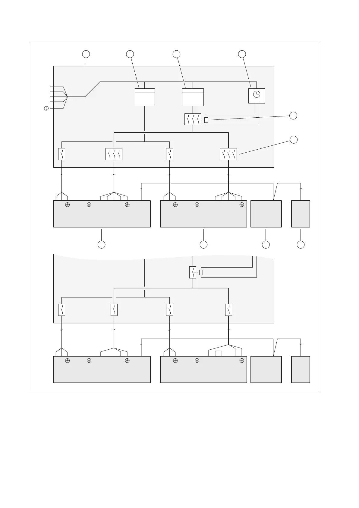
E Basic connection diagram for the energy supply company lockout, shutdown via
partition
3~/400V 1~/230V
3
3
L1 L2 L3
NL
N
X200
BUS
X206X210
LN
X211
BUSS21 BUS
X106
L1L1 L2 L3 NLN
X300X311
LN
X310
kWh
N
L1
L2
L3
kWh
L1 L2 L3 NLN
X200
BUS
X206
X210
LN
X211
BUSS21 BUS
X106
L1L1 L2 L3 NLN
X300X311
LN
X310
5 5
2
2
22
3
3
3 3
1 2 3 4
5
6
78910
1 Meter/fuse box
2 Household electricity meter
3 Heat pump electricity meter
4 Ripple control receiver
5 Partition, for the energy supply company lockout
function
6 Disconnector (circuit breaker, fuse)
7 System control
8 Indoor unit, control PCB
9 Indoor unit, power supply PCB
10 Outdoor unit, PCB INSTALLER BOARD