22 Operating and installation instructions 0020288151_04
3 -- Electrical installation, set-up
Obstacles weaken the reception strength between the radio
receiver unit and the system control or outdoor temperature
sensor.
Only qualified electricians may carry out the electrical install-
ation.
The heating installation must be decommissioned before
work is carried out on it.
3.1 Checking the scope of delivery
Quantity Contents
1 System control
1 Radio receiver unit
1 VR 20 outdoor temperature sensor or VR 21 out-
door temperature sensor
1 Fixing material (2 screws and 2 wall plugs)
4 Batteries, LR06
1 Documentation
▶ Check that the scope of delivery is complete and intact.
3.2 Requirements for the eBUS line
Observe the following rules when routing the eBUS lines:
▶ Use twin-core cables.
▶ Never use shielded or twisted cables.
▶ Use only appropriate cables, e.g. NYM or H05VV (-F/-U).
▶ Observe the permissible total length of 125 m. In this
case, a conductor cross-section of ≥ 0.75 mm² up to
50 m total length and a conductor cross-section of
1.5 mm² from 50 m.
In order to prevent faults in the eBUS signals (e.g. due to
interferences):
▶ Maintain a minimum clearance of 120 mm to power sup-
ply cables or other electromagnetic sources of interfer-
ence.
▶ For parallel routing to mains connection lines, guide the
cables in accordance with the applicable regulations, e.g.
on cable trays.
▶ Exceptions: For wall breaks and in the electronics box, it
is acceptable to not reach the minimum clearance.
3.3 Requirements for the sensor cable
Observe the following rules when routing the sensor lines:
▶ Use twin-core cables.
▶ Never use shielded or twisted cables.
▶ Use only appropriate cables, e.g. NYM or H05VV (-F/-U).
▶ Observe the permissible total length of 50 m.
In order to prevent faults in the sensor signals (e.g. due to
interferences):
▶ Maintain a minimum clearance of 120 mm to power sup-
ply cables or other electromagnetic sources of interfer-
ence.
▶ For parallel routing to mains connection lines, guide the
cables in accordance with the applicable regulations, e.g.
on cable trays.
▶ Exceptions: For wall breaks and in the electronics box, it
is acceptable to not reach the minimum clearance.
3.4 Installing the radio receiver unit
The radio receiver unit can be installed on a heat generator
or on a ventilation unit with connected heat generators.
When installing the radio receiver unit on a heat generator,
the radio receiver unit can also be wall-mounted outside of
wet environments in order to improve the reception strength
and it can be connected using an extension cable.
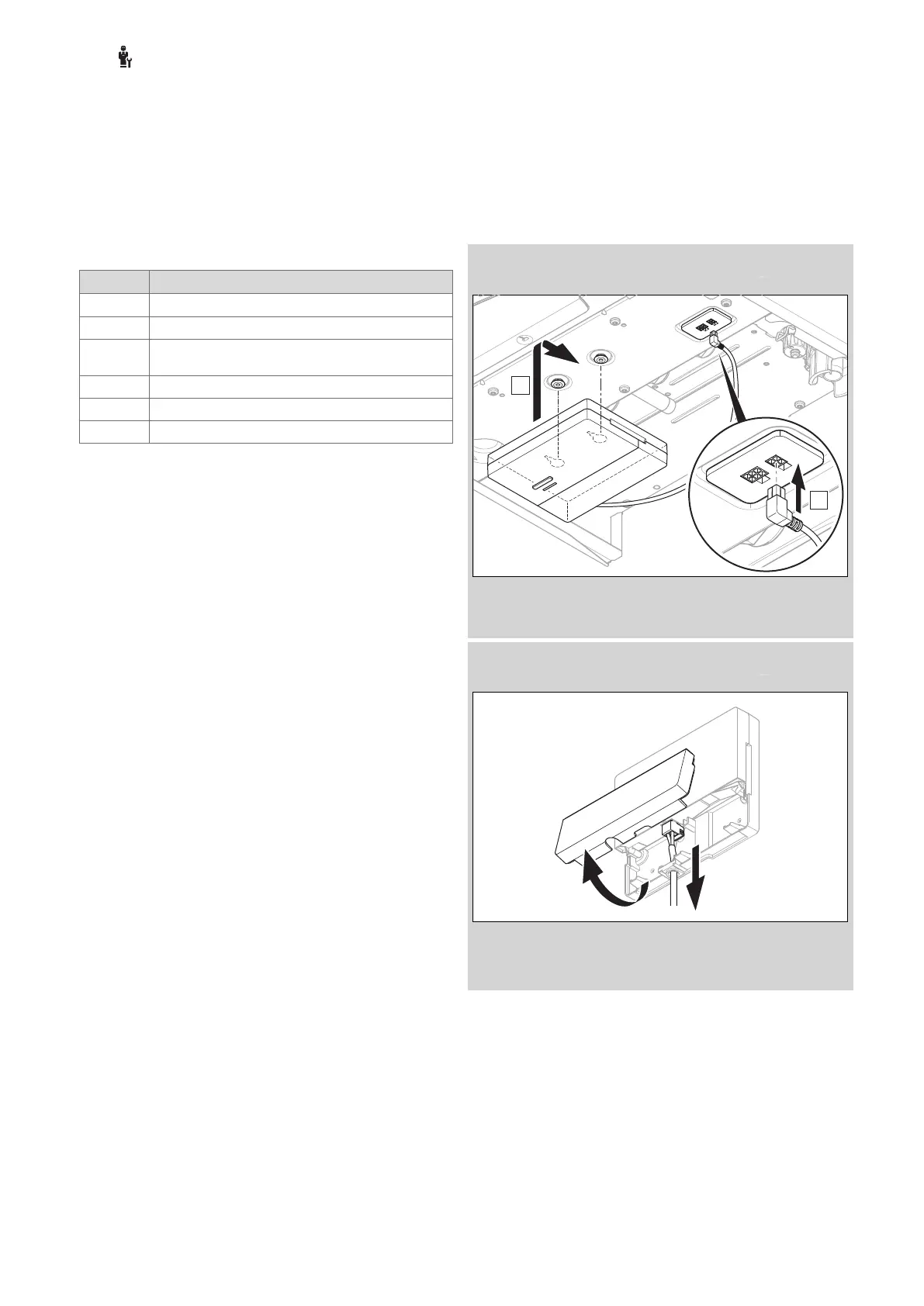
3.4.1 Installing the radio receiver unit and
connecting to the heat generator
Condition: The heat generator has an option to connect it directly and is not
installed in the wet environment.
▶ Install the radio receiver unit below the heat generator.
▶ Connect the radio receiver unit to the direct connection
below the heat generator.
Condition: The heat generator does not have an option to connect it directly
and/or is installed in the wet environment.
▶ Remove the flap on the radio receiver unit in accordance
with the figure.
▶ Remove the existing cable for the direct connection.