0020288151_04 Operating and installation instructions 31
Sensor assignment
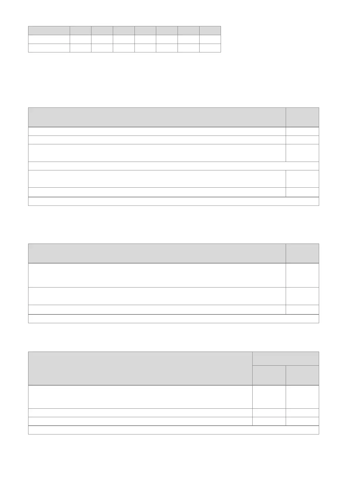
Configuration S1 S2 S3 S4 S5 S6 S7
FM3+FM5 – – – – VR 10 VR 10 –
FM3 VR 10 – – – VR 10 VR 10 –
4.7 Settings for the basic system diagram codes
The systems are roughly grouped according to their connected system components. Each grouping contains a basic system
diagram code that you must enter in the Basic system diagram code: function in the system control. The system control
requires the basic system diagram code in order to enable the system-related functions.
4.7.1 Gas- or oil-fired boiler as a single unit
System property Basic sys-
tem dia-
gram code:
allSTOR cylinder system incl. domestic hot water station 1
Boilers with solar domestic hot water support 1
All boilers without solar
– Connecting the domestic hot water cylinder temperature sensor to the boiler
1
Exceptions:
Boilers without solar
– Connecting the domestic hot water cylinder temperature sensor to the functional module
2
1)
Boiler with solar heating and hot water support
2
1)
1) Do not use the integrated prioritising diverter valve from the ecoTEC VC boiler (permanent position: Heating mode).
4.7.2 Cascade with gas- or oil-fired boilers
Maximum seven boilers possible
As of the second boiler, the boilers are connected via VR 32 (address 2 to 7).
System property Basic sys-
tem dia-
gram code:
Domestic hot water generation provided by a selected boiler (isolating circuit)
– Domestic hot water generation provided by the boiler with the highest address
– Connecting a domestic hot water cylinder temperature sensor to this boiler
1
Domestic hot water generation provided by the whole cascade (no isolating circuit)
– Connecting the domestic hot water cylinder temperature sensor to the FM5 functional module
2
1)
allSTOR cylinder system incl. domestic hot water station
2
1)
1) Do not use the integrated prioritising diverter valve from the ecoTEC VC boiler (permanent position: Heating mode).
4.7.3 Heat pump as a single unit (monoenergetic)
With immersion heater in the flow as a back-up boiler
System property Basic system diagram
code:
Without
heat ex-
changer
1)
With heat
exchanger
1)
Without solar
– Connecting the domestic hot water cylinder temperature sensor to the heat pump control module
and/or heat pump
8 11
With solar domestic hot water support 8 11
allSTOR cylinder system incl. domestic hot water station 8 16
1) E.g. VWZ MWT