30 Operating and installation instructions 0020288151_04
Configur-
ation
S1 S2 S3 S4 S5 S6 S7 S8 S9 S10 S11 S12 S13
6 SysFlow FS1 FS2 FS3 BufBt BufBtCH BufTop
DHW
BufBt
DHW
DEM1 DEM2 DEM3 DHW
Bt2
–
Meaning of the abbreviations (→ Section 4.9.2)
Sensor assignment
Configura-
tion
S1 S2 S3 S4 S5 S6 S7 S8 S9 S10 S11 S12 S13
1 VR 10 VR 10 VR 10 VR 10 VR 10 VR 10 VR 11 VR 10 – VR 10 VR 10 – –
2 VR 10 VR 10 VR 10 VR 10 VR 10 VR 10 VR 11 VR 10 – VR 10 VR 10 – –
3 VR 10 VR 10 VR 10 VR 10 VR 10 – – – VR 10 VR 10 – – –
6 VR 10 VR 10 VR 10 VR 10 VR 10 VR 10 VR 10 VR 10 – – – VR 10 –
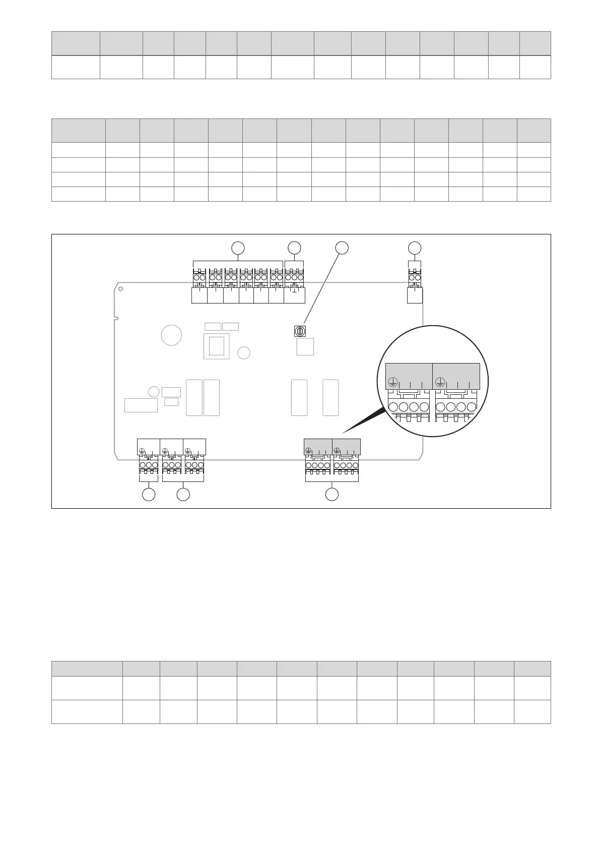
4.6 Connection assignment for the FM3 functional module
S1
12
S2
12
S3
12
S4
12
S5
12
S6
12
S7
OI
R3/4
N
1
2
R5/6
N
1
2
R2
L
N
R1
L
N
230V
L
N
BUS
-+
5
67
1
2
4
3
1 Input sensor terminals
2 Signal terminal
3 Address switch
4 eBUS terminal
5 Mixer output
6 Output relay terminals
7 Power supply
S2, S3 sensor terminals: An external control can also be connected
R3/4, R5/6 mixer output: 1 = open, 2 = closed
You can configure the contacts for external inputs in the system control.
– Open, deact.: Contacts open, no heat demand
– Bridge,deact.: Contacts closed, no heat demand
Configuration R1 R2 R3/R4 R5/R6 S1 S2 S3 S4 S5 S6 S7
FM3+FM5 3fa 3fb 9kaop/
9kacl
9kbop/
9kbcl
– DEMa DEMb – FSa FSb –
FM3 3f1 3f2 MO 9k2op/
9k2cl
BufBt/
DHW
DEM1 DEM2 – SysFlow FS2 –
Meaning of the abbreviations (→ Section 4.9.2)