Product description 3
0020257319_02 Hydraulic station Installation and maintenance instructions 21
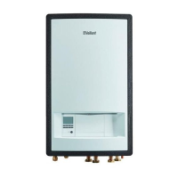
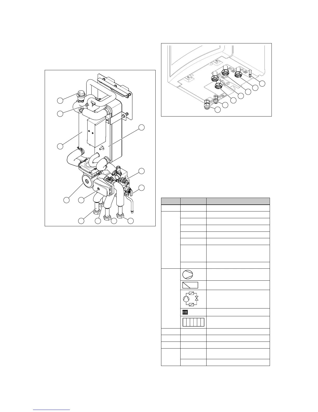
3 Hydraulic block
4 Electronics box with
PCB
5 Indoor unit control
6 Electronics box (for
back-up immersion
heater)
3.6.2 Design of the hydraulic block
1 Condenser
2 Pressure sensor (heat-
ing circuit)
3 Expansion relief valve
4 Heating return
5 Heating flow
6 Domestic hot water
cylinder return
7 Domestic hot water
cylinder flow
8 Prioritising diverter
valve (heating cir-
cuit/cylinder charging)
9 Heating pump
10 Electric back-up heater
11 Service valve for filling
and creating a vacuum
in the refrigerant circuit
12 Automatic air vent
3.6.3 Underside of the product
1 Drain for expansion
relief valve
2 Heating return
3 Heating flow
4 Domestic hot water
cylinder flow
5 Domestic hot water
cylinder return
6 Liquid pipe connection
7 Hot gas pipe connection
3.7 Service valve
At the service valve, you can test the vacuum, carry out
pressure tests, and fill the refrigerant circuit.
3.8 Information on the data plate
The data plate is located on the rear of the electronics box.
Information Meaning
Serial no. Unique unit identification number
Nomen-
clature
VWL Vaillant, heat pump, air
5, 7, 12 Heating output in kW
7 Heating mode or cooling mode
/5 Unit generation
IS Indoor unit, split technology
230 V Electrical connection:
230 V: 1~/N/PE 230 V
400 V: 3~/N/PE 400 V
IP Protection class
Symbols
Compressor
Control
Refrigerant circuit
Heating circuit
Back-up heater
P max Rated power, maximum
I max Rated current, maximum
I In-rush current
Refri-
gerant
circuit
MPa (bar) Permissible operating pressure (rel-
ative)
R410A Refrigerant, type
 Loading...