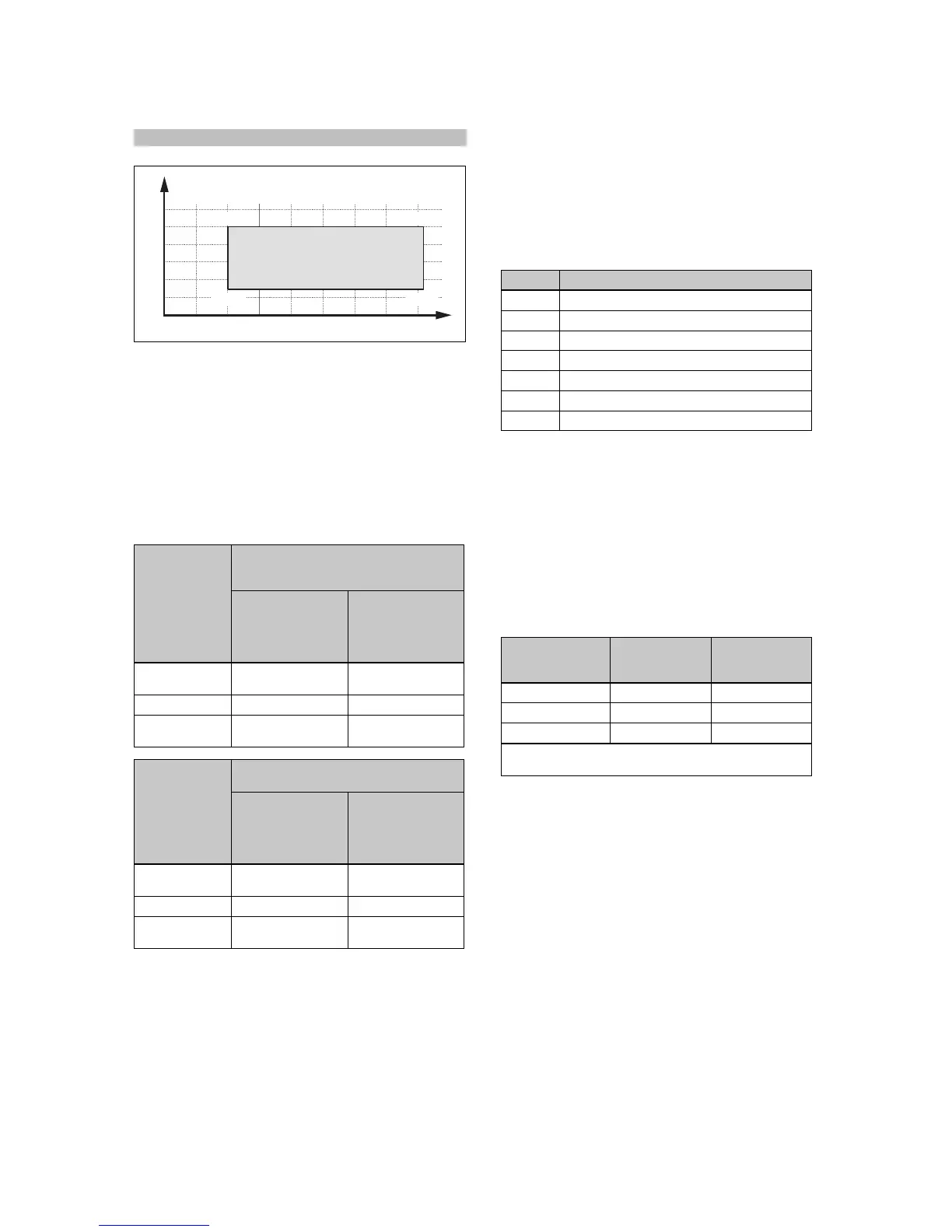
A Outdoor temperature B Heating water temperat-
ure
3.12 Buffer cylinder
Heating installations, which mainly consist of fan coils or ra-
diators, usually contain a low volume of water. We recom-
mend installing a buffer cylinder. In the case of two or more
heating circuits in the system, a buffer cylinder or a low loss
header should also be used as decoupling.
For the outdoor unit, it is important for the evaporator's de-
icing process that sufficient thermal energy can be provided.
Heat pump in
the split system
Minimum installation volume
For heating circuit with underfloor heat-
ing and fan coils
When the heating
system is active
in winter and the
back-up heater is
deactivated
When the heating
system is active
in winter and the
back-up heater is
active
3 kW and 5 kW
output
40 l 15 l
7 kW output 55 l 20 l
10 kW and
12 kW output
150 l 45 l
Heat pump in
the split system
Minimum installation volume
For heating circuit with radiators
When the heating
system is active
in winter and the
back-up heater is
deactivated
When the heating
system is active
in winter and the
back-up heater is
active
3 kW and 5 kW
output
100 l 20 l
7 kW output 130 l 30 l
10 kW and
12 kW output
250 l 50 l
4 Set-up
4.1 Unpacking the product
1. Remove the product from the packaging.
2. Remove the documentation.
3. Remove the protective film from all parts of the product.
4.2 Checking the scope of delivery
▶ Check that the scope of delivery is complete and intact.
Number Designation
1
Hydraulic station
1
Enclosed documentation
1
Bag with installation material
1 Selection lever for prioritising diverter valve
1 Filling device
1 5-pole 400 V connection cable
1 Adhesive strips for noise reduction
4.3 Selecting the installation site
▶ The installation site must be below 2000 metres above
sea level.
▶ Select a dry room that is frost-proof throughout and in
which the maximum installation height is not exceeded
and the environmental temperature is neither above nor
below the permitted range.
– Permissible environmental temperature: 7 … 25 ℃
– Permissible relative air humidity: 40 … 75 %
▶ Ensure that the installation room has the required min-
imum volume.
Heat pump R410A refri-
gerant filling
volume
Minimum in-
stallation room
volume
VWL 57/5 IS 1.5 kg 3.41 m³
VWL 77/5 IS 2.4 kg 5.45 m³
VWL 127/5 IS 3.6 kg 8.18 m³
Minimum installation room = refrigerant filling volume
(kg)/practical limit value (kg/m³) (for R410A = 0.44 kg/m³)
▶ Ensure that the required minimum clearances can be
maintained.
▶ Observe the permissible height difference between out-
door unit and indoor unit. See the technical data in the
appendix.
▶ When selecting the installation site, you must take into
consideration that when the heat pump is in operation, it
will transfer vibrations to the walls.
▶ Ensure that the wall is even and offers sufficient load-
bearing capacity to bear the weight of the product.
▶ Ensure that pipes can be easily routed in an appropriate
way (domestic hot water side, heating side and refriger-
ant side).
▶ Do not install the product above another unit that may
damage it (e.g. above a cooker that produces water va-
pour and grease) or in a room with a high level of expos-
ure to dust or in a corrosive environment.
▶ Do not install the product below a unit from which liquids
may flow.
 Loading...