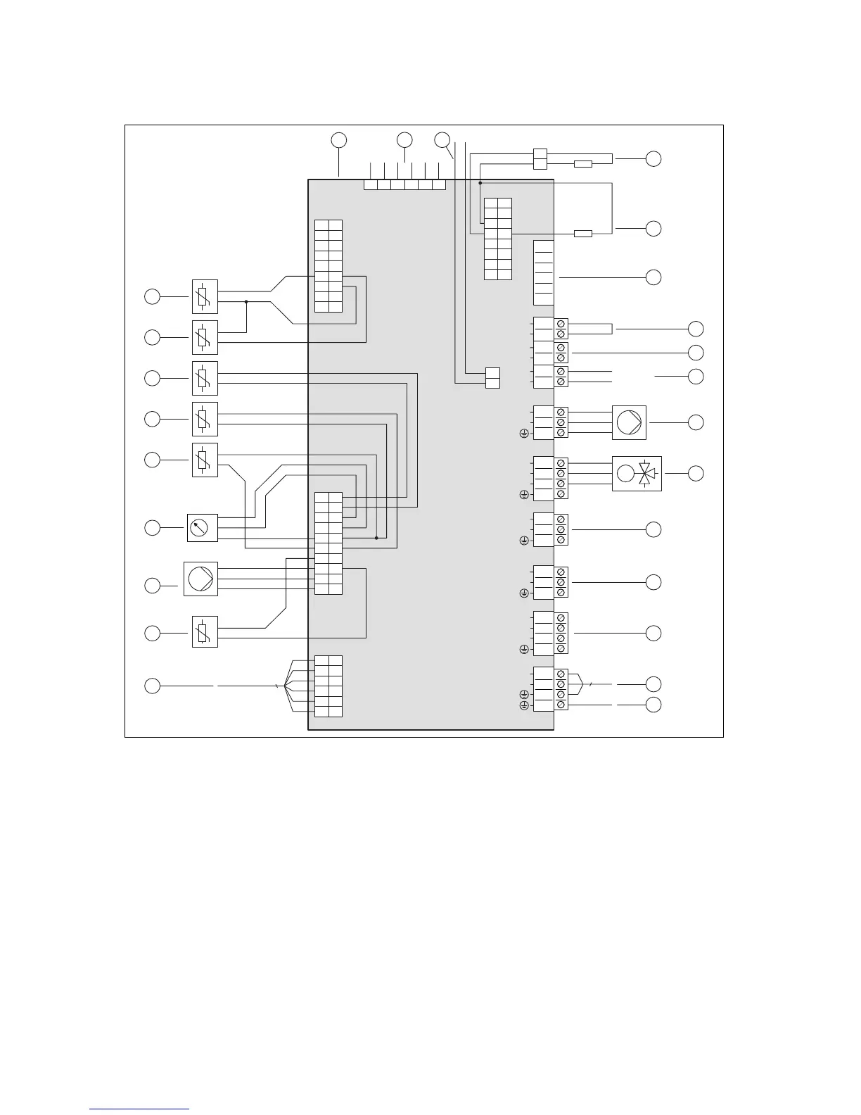
1 Control PCB
2 [X51] Display edge connector
3 [X29] eBUS bus connection for the installed system
control
4 [X24] Coding resistor 3
5 [X24] Coding resistor 2
6 [X41] Edge connector (outdoor temperature sensor,
DCF, system temperature sensor, multi-function
input)
7 [X106/S20] Limit thermostat
8 [X106/S21] ESCO contact
9 [X106/BUS] eBUS bus connection (outdoor unit,
VRC 700, VR 70 / VR 71 )
10 [X16] Internal heating pump
11 [X15] Internal prioritising diverter valve for heating
circuit/cylinder charging
12 [X11] Multi-function output 2: Domestic hot water
circulation pump
13 [X13] Multi-function output 1
14 [X14] Multi-function output: External back-up
heater/external prioritising diverter valve
15 [X1] 230 V supply for control PCB
16 Earth wire for the power supply PCB
17 [X28] Data connection to the power supply PCB
18 [X22] Immersion heater flow temperature sensor
19 [X22] Heating pump signal
20 [X22] Pressure sensor
21 [X22] Building circuit flow temperature sensor
22 [X22] Building circuit return temperature sensor
23 [X22] Domestic hot water cylinder temperature
sensor
24 [X21] Condenser outlet temperature sensor (EEV
outlet)
25 [X21] Condenser inlet temperature sensor
 Loading...