6 Electrical installation
28 Installation and maintenance instructions Hydraulic station 0020257319_02
1. Observe the technical connection conditions for con-
necting to the energy supply company's low-voltage
network.
2. Use the data plate to determine whether the product
requires a 1~/230V or a 3~/400V electrical connection.
3. The product is preconfigured for the unblocked 1~/230V
connection.
4. Determine whether the power supply for the product
should be set up with a single-tariff meter or a dual-tariff
meter.
5. Ensure that the nominal voltage of the single-phase
network is 230 V (+10%/-15%) and the nominal voltage
of the 3-phase network is 400 V (+10–15%).
6. Connect the product using a fixed connection and a
partition with a contact gap of at least 3 mm (e.g. fuses
or power switches).
7. Use the data plate to determine the product's rated
current. Derive the suitable cable cross-sections
for the electrical wires from this. The requirements
for the cables can be found in from (→ Page 28) to
(→ Page 29).
8. In each case, take into consideration the (on-site) in-
stallation conditions.
9. Ensure that the nominal voltage of the power grid cor-
responds to that of the product's main power supply
cabling.
10. Make sure that access to the power supply is always
available and is not covered or blocked.
11. If the local power supply network operator requires that
the heat pump is controlled using a blocking signal,
install a corresponding contact switch as prescribed
by the power supply network operator.
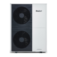
6.2 Opening the power supply PCB's electronics
box
1. Remove the front casing. (→ Page 25)
1. Remove the front casing. (→ Page 25)
2. Open the power supply PCB's electronics box.
(→ Page 28)
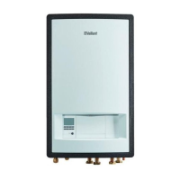
3. Guide the power supply cable (3) and other power sup-
ply cables (230 V) (4) through the central unit opening
and into the product.
4. Guide the eBUS cable (1) and other low-voltage con-
nection cables (24 V) (2) through the left-hand unit
opening and into the product.
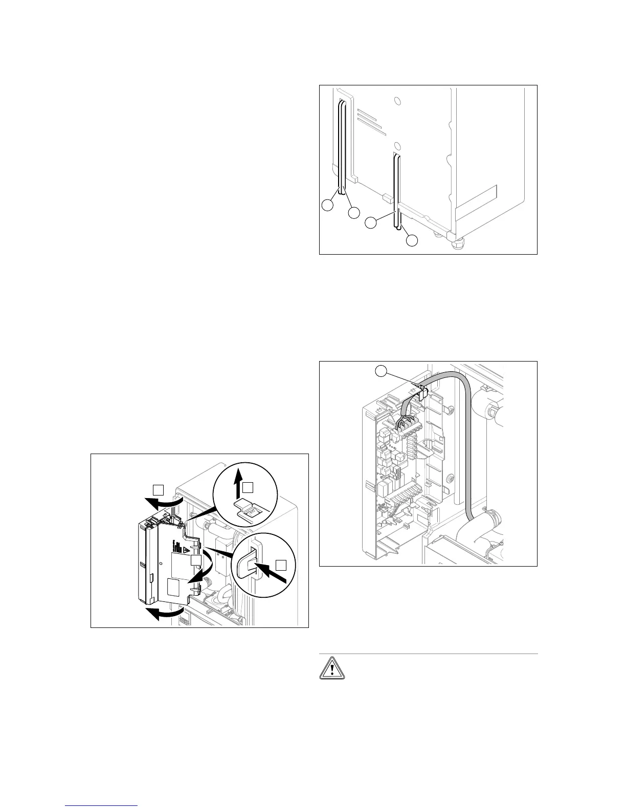
5. Guide the power supply cables through the strain relief
(1) to the terminals on the power supply PCB.
6. Connect the power supply cable to the corresponding
terminals.
7. Secure the power supply cable in the strain reliefs.
6.3.1 1~/230V single power supply
Caution.
Risk of material damage due to high con-
nected voltage.
With excessive mains voltages, electronic
components may be damaged.
 Loading...