Electrical installation 6
0020257319_02 Hydraulic station Installation and maintenance instructions 29
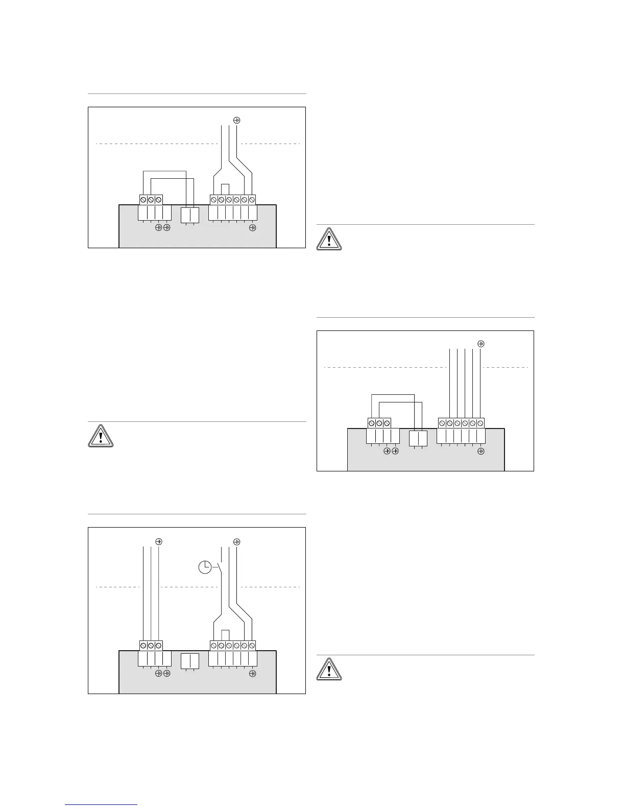
▶ Ensure that the mains voltage is in the
permissible range.
1
2
3
4
5
6
L1
L1
L2
L3
N
X300X310X311
2
1
L1
N
3
4
1
2
N
L
N
L
1. Install a separate type B residual-current circuit breaker
for the product.
2. Note the specifications on the sticker on the electronics
box.
3. Use a 3-pole power supply cable with a conductor
cross-section of 4 mm
2
and a temperature resistance of
90 °C.
4. Remove the cable jacket until there is only 30 mm left.
5. Connect the power supply cable to L1, N, PE, as
shown.
6. Use the strain relief clamp to secure the cable in place.
7. Observe the instructions on connecting a dual-tariff
supply; see (→ Page 30).
6.3.2 1~/230V dual power supply
Caution.
Risk of material damage due to high con-
nected voltage.
With excessive mains voltages, electronic
components may be damaged.
▶ Ensure that the mains voltage is in the
permissible range.
1
2
3
4
5
6
L1
L1
L2
L3
N
X300X310X311
2
1
L1
N
3
4
1
2
N
L
N
L
N
L
1. Install a separate type B residual-current circuit breaker
for the product.
2. Note the specifications on the sticker on the electronics
box.
3. Use a 3-pole power supply cable (low tariff) with a con-
ductor cross-section of 4 mm
2
and a temperature resist-
ance of 90 °C. Use a 3-pole power supply cable (high
tariff) with a conductor cross-section of 0.75 mm
2
and a
temperature resistance of 90 °C.
4. Remove the cable jacket until there is only 30 mm left.
5. Connect the power supply cable, as shown.
6. Use the strain relief clamp to secure the cable in place.
7. Observe the instructions on connecting a dual-tariff
supply; see (→ Page 30).
6.3.3 3~/400V single power supply
Caution.
Risk of material damage due to high con-
nected voltage.
With excessive mains voltages, electronic
components may be damaged.
▶ Ensure that the mains voltage is in the
permissible range.
1
2
3
4
5
6
L1
L1
L2
L3
N
L1
L2
L3
N
X300X310X311
2
1
L1
N
3
4
1
2
N
L
L
1. Install a separate type B residual-current circuit breaker
for the product.
2. Note the specifications on the sticker on the electronics
box.
3. Use a 5-pole power supply cable with a conductor
cross-section of 2.5 mm
2
and a temperature resistance
of 90 °C.
4. Remove the cable jacket until there is only 70 mm left.
5. Remove the jumper from between connections L1 and
L2.
6. Connect the power supply cable to L1, L2, L3, N, PE,
as shown.
7. Observe the instructions on connecting a dual-tariff
supply; see (→ Page 30).
6.3.4 3~/400V dual power supply
Caution.
Risk of material damage due to high con-
nected voltage.
With excessive mains voltages, electronic
components may be damaged.
 Loading...