EasyManuals Logo

Vaillant VWL 127/5 IS User Manual

Vaillant VWL 127/5 IS
72 pages
To Next Page IconTo Next Page
To Previous Page IconTo Previous Page
Page #47 background imageLoading...
Page #47 background image
Appendix
0020257319_02 Hydraulic station Installation and maintenance instructions 45
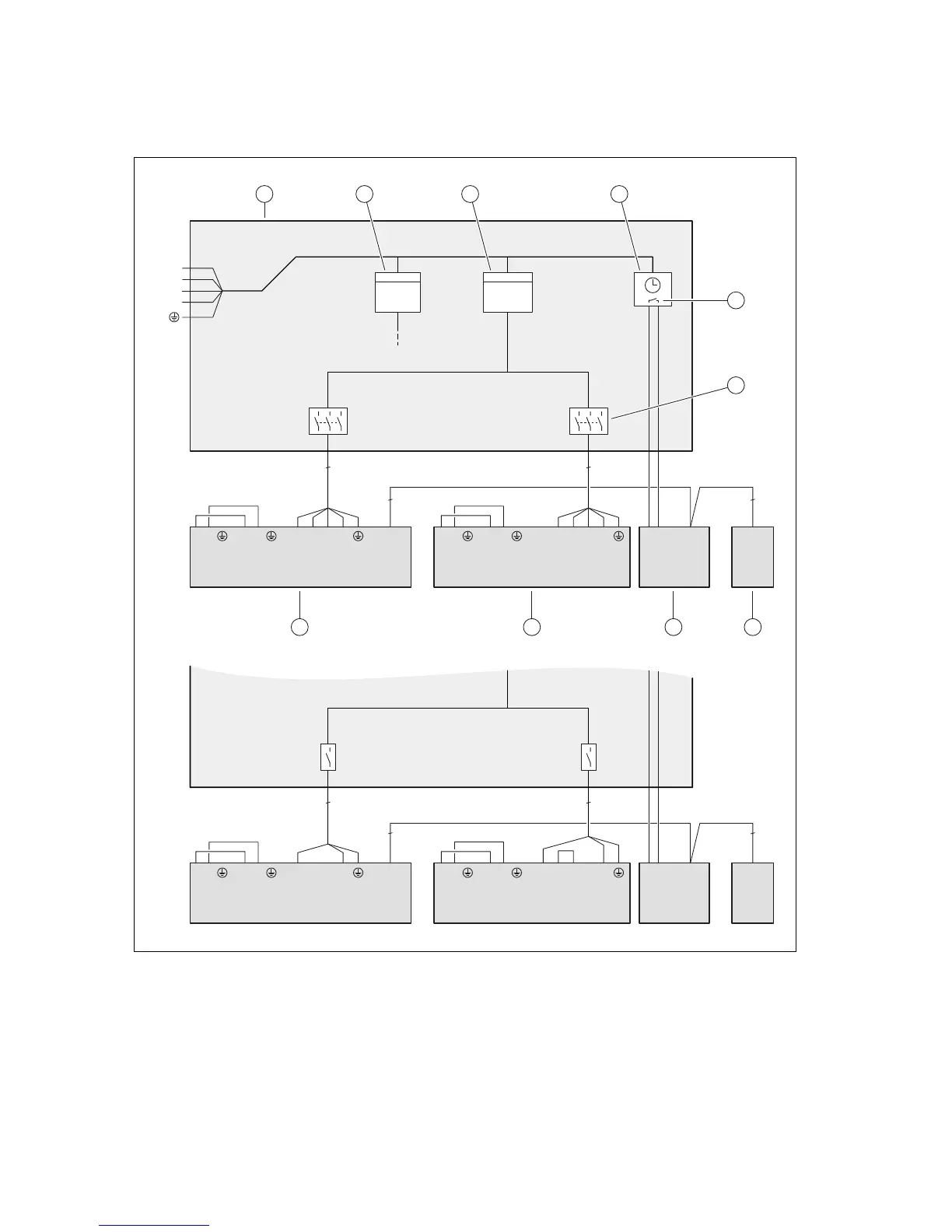
C Basic connection diagram for the energy supply company lockout, shutdown via
connection S21
3~/400V
1~/230V
BUSS21 BUS
X106
L1L1 L2 L3 NLN
X300X311
LN
X310
kWh
L1 L2 L3 NLN
X200
BUS
X206X210
LN
X211
kWh
2
2
N
L1
L2
L3
5 5
BUSS21 BUS
X106
L1L1 L2 L3 NLN
X300X311
LN
X310
L1 L2 L3 NL N
X200
BUS
X206X210
LN
X211
2
2
3 3
1 2 3 4
5
6
78910
1 Meter/fuse box
2 Household electricity meter
3 Heat pump electricity meter
4 Ripple control receiver
5 Potential-free normally open contact, for actuating
S21, for the energy supply company lockout function
6 Disconnector (circuit breaker, fuse)
7 System control
8 Indoor unit, control PCB
9 Indoor unit, power supply PCB
10 Outdoor unit, PCB INSTALLER BOARD

Table of Contents

Questions and Answers:

Question and Answer IconNeed help?

Do you have a question about the Vaillant VWL 127/5 IS and is the answer not in the manual?

Vaillant VWL 127/5 IS Specifications

General IconGeneral
BrandVaillant
ModelVWL 127/5 IS
CategoryHeat Pump
LanguageEnglish

Related product manuals