48 Rainger Linear
OPERATION
Hose Inlets and Couplers
There are two different hose inlets, the Side Inlet and the Center Inlet.
• Side Inlet hose layout and
basic method of operation
begins on the next page.
• Center Inlet hose layout
and basic method of opera-
tion begins on page 53.
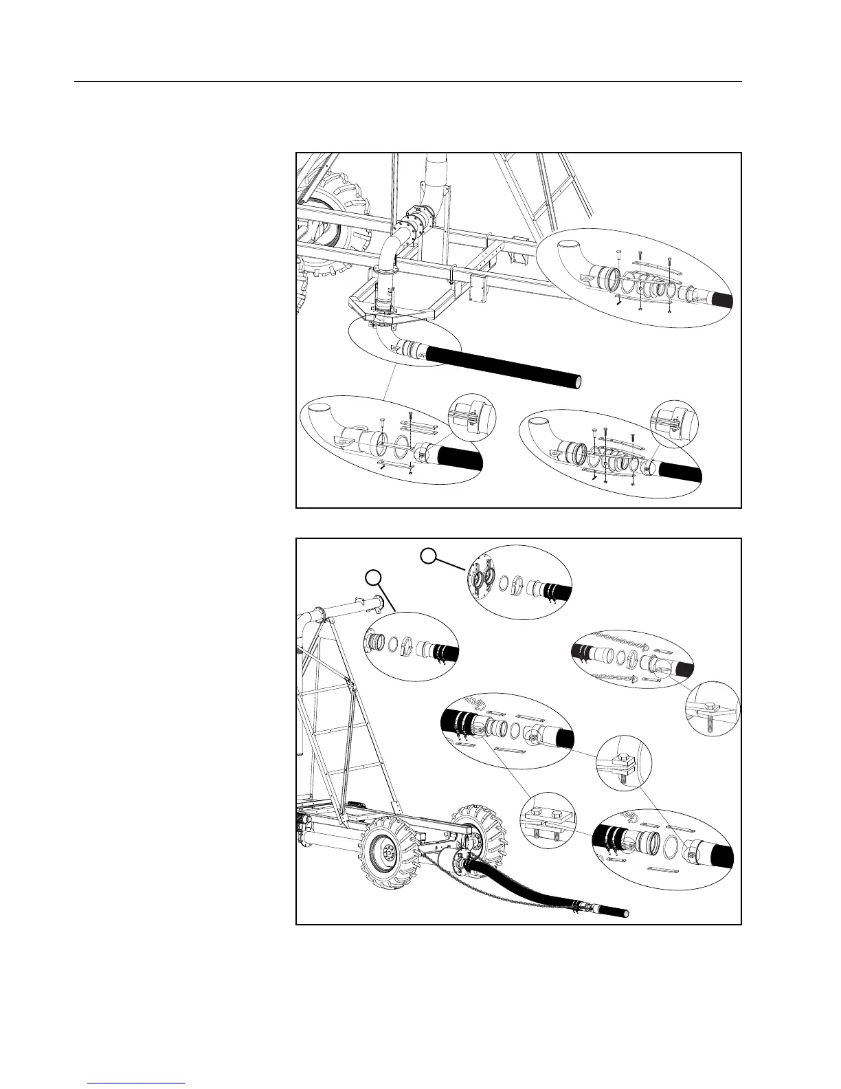
• Hose coupler design varies
depending on the type and
size of the hose. See Fig-
ures 48-1 and 48-2.
• Side inlet hose couplers
are secured to the inlet
with pull straps. See Figure
48-1.
• Center inlet hose couplers
are secured to the inlet with
a circle lock ring. See Fig-
ure 48-2.
• The center inlet uses soft
hose on the inlet end of the
hose. See Figure 48-2.
• Soft hose requires the use
of chains to pull the poly
hose. See Figure 48-2.
• There are two types of
center inlet. Single inlet for
8 inch hose or double inlet
for all other sizes of hose.
See Figure 48-2.
Figure 48-1 Side Inlet Hose Couplers
1
2
Figure 48-2 Center Inlet Hose Couplers, Soft hose and Chains
1. Single Inlet
2. Double Inlet