62 Rainger Linear
OPERATION
Open Delivery
Start Up - Engine Generator Pump Applications
1. Inspect the wheel tracks to insure no vehicles or
other equipment will be contacted upon start-up
or operation.
2. Turn on the oscillator, if the system has below
ground guidance.
3. Check the engine fuel, coolant, and oil levels. Fill
as needed.
4. Check the centrifugal pump oil reservoir level. Fill
as needed.
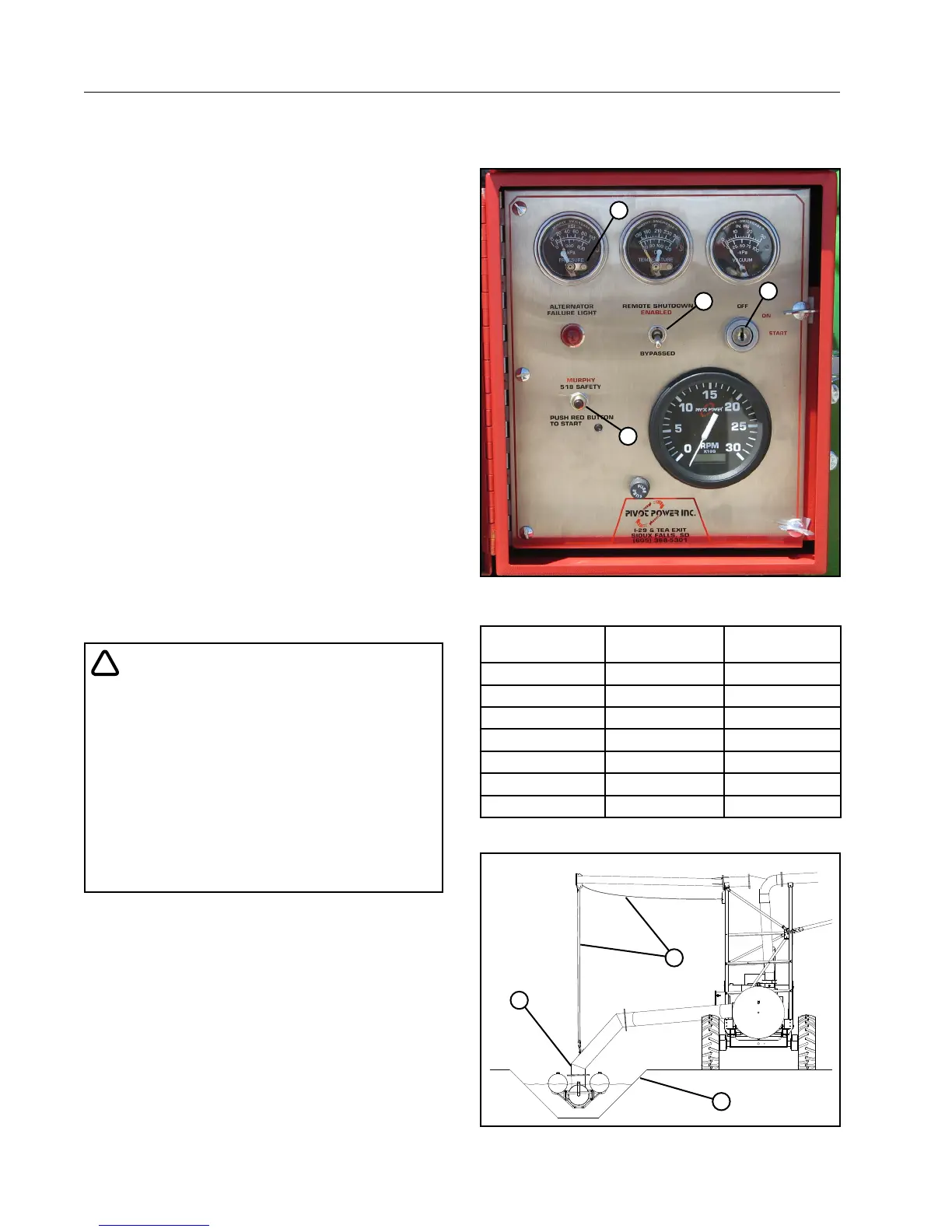
5. At the engine control panel, move the Remote
Shutdown toggle switch to the Bypassed posi-
tion. See Figure 62-2.
6. Push the Reset button on the water pressure
gauge.
7. Push and hold the red Safety button in while
turning the Engine Start switch to START. When
the engine starts, turn the Engine Start switch to
the ON position and the safety button will hold
itself in.
8. Turn the control panel disconnect to the ON posi-
tion.
9. Check the voltmeter reading and verify that the
generator is producing the correct Nominal Sup-
ply Voltage for this machine. See Figure 62-3.
!
CAUTION
• DO NOT OPERATE THE MACHINE IF THE
VOLT METER READS BELOW THE MINIMUM
ALLOWED VOLTAGE OR ABOVE THE MAXI-
MUM ALLOWED VOLTAGE. SEE FIGURE 62-2.
• OPERATING THE MACHINE OUTSIDE THESE
LIMITS COULD CAUSE DAMAGE TO THE
DRIVE MOTORS AND OTHER ELECTRICAL
COMPONENTS.
• CORRECT THE LOW VOLTAGE PROBLEM
BEFORE RESUMING OPERATION.
10. Determine if the machine will be run wet or dry.
• If running the machine wet, with water,
(a) Lower suction inlet into ditch until the inlet
lift cables go slack. See Figure 62-1.
(b) Prime the centrifugal pump. See Exhaust
Primer on page 59, Compressed Air
Primer on page 59 or 12 VDC Electric
Primer on page 60. After the pump is
primed return to this instruction.
(c) Continue with step 11.
• If running the machine dry, without water,
raise the suction inlet completely out of the
ditch, then continue with step 12.
3
1
2
4
Figure 62-1 1. Safety Button
2. Toggle Switch
3. Engine Start Switch
4. Water Pressure Gauge Reset
Nominal
Supply Voltage
Maximum
Allowed Voltage
Minimum
Allowed Voltage
480 VAC @ 60Hz 505 VAC 440 VAC
415 VAC @ 50Hz 420 VAC 375 VAC
400 VAC @ 50Hz 420 VAC 365 VAC
380 VAC @ 50Hz 420 VAC 355 VAC
230 VAC @ 60Hz 253 VAC 220 VAC
120 VAC @ 60Hz 132 VAC 105 VAC
110 VAC @ 50Hz 121 VAC 95 VAC
Figure 62-2
1
3
2
Figure 62-3 1. Suction Inlet
2. Ditch
3. Lift Cable