Rainger Linear 53
OPERATION
Center Inlet
Hose and Cord Layout
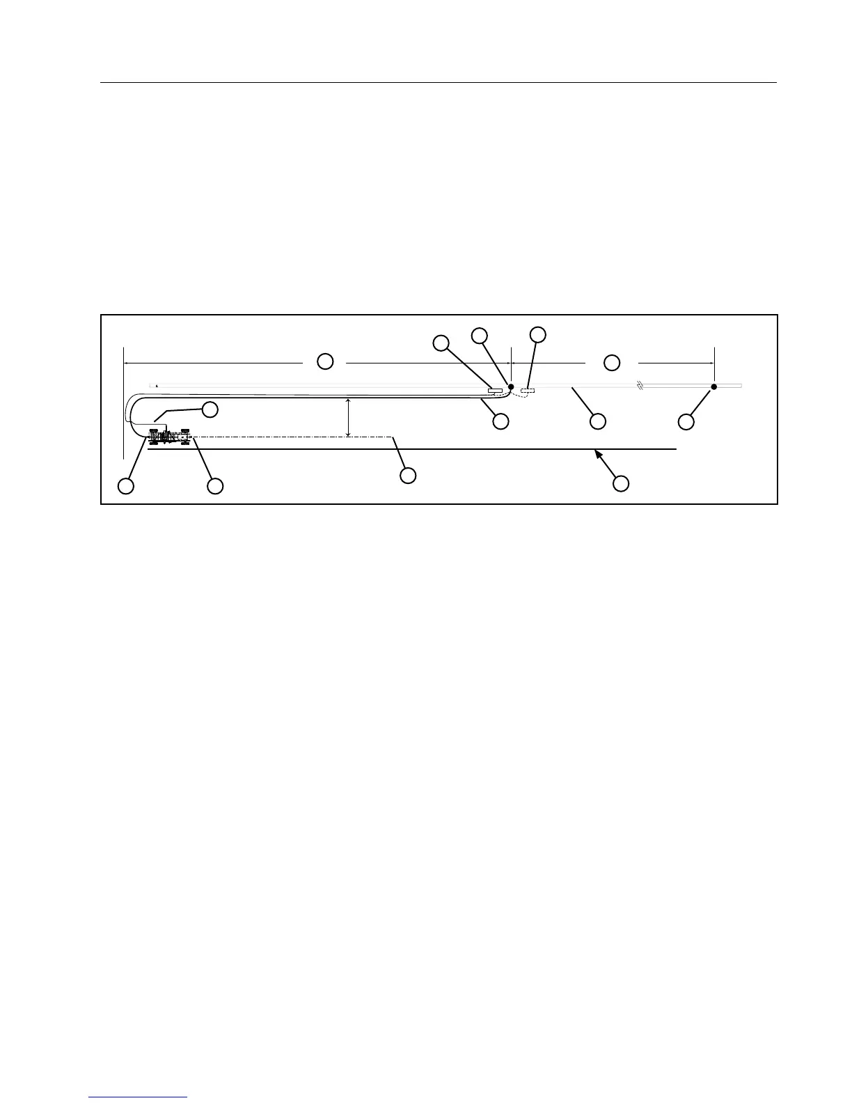
• When using the center inlet, position the hose as shown. See Figure 53-1.
• The cart path must be maintained in a smooth, hard condition, to allow the poly hose to slide freely over
the surface.
• The hose must be disconnected from the cart, repositioned and then connected to the other end of cart
when reversing direction.
• If using the optional electric cord drag with the center inlet, position the electric cord far enough away from
the hose, so that the hose will not drag over it. When applicable, prevent interference between the electric
cord and hose by positioning the electric cord over the top of hose or burying the electric cord at point of
anticipated interference. See Figure 53-1.
.
32 ft
(9.75 m)
2
5
8
1
4
7
3
1
6
9
10
11
12
Figure 53-1 1. Center Inlet
2. 8 in Hose
3. Water Pipeline
4. First Riser
5. Intermediate Riser
6. Electric Cord (optional)
7. Power Pedestal
8. Alternate Power Pedestal Location
and Electric Cord Position
9. Centerline of Cart
10. End of field to first riser = (poly hose length - 50 ft (15.24 m)
11. Intermediate riser spacing = (2 x poly hose length - 80 ft (24.38 m))
12. Guidance Furrow or Cable