88 Rainger Linear
MAINTENANCE
Machine Alignment
Modified Alignment Adjustment
When a machine is equipped with modified align-
ment the tower box is located on the side of the tower
with a mechanical linkage between the tower box and
the control bar.
NOTE
• All adjustments shown are made from the
tower box side of drive unit.
1. From the tower box side of drive unit, loosen the
jam nut at each end of the connection rod. See
Figures 88-1 and 88-2.
2. To adjust the distance between the control bar
and the switch pivot arm, rotate the connection
rod clockwise or counter-clockwise no more than
1/8 of a turn at one time. See Figures 88-1 and
88-2, and the adjustment chart below.
ADJUSTMENT CHART
Direction of travel Condition Adjust Nuts
Forward
Leading Bow **Counter-clockwise
Trailing Bow *Clockwise
Reverse
Leading Bow *Clockwise
Trailing Bow **Counter-clockwise
* Clockwise - From the tower box side of the drive
tower, rotate the connection rod clockwise to in-
crease the distance between the control bar and
the switch pivot arm.
** Counter-clockwise - From the tower box side of the
drive tower, rotate the connection rod counter-clock-
wise to decrease the distance between the control bar
and the switch pivot arm.
!
CAUTION
• NEVER ADJUST THE CONNECTION ROD
MORE THAN 1/8 OF A TURN AT ONE TIME.
• ALWAYS RE-TIGHTEN THE JAM NUTS AND
ALLOW THE TOWER TO CYCLE TWICE
(START AND STOP) TO DETERMINE IF THE
TOWER IS STILL LEADING OR TRAILING.
3. Adjust the connection rod until the tower is in
alignment.
• Sensitivity can be adjusted by repositioning
the connection rod. See Figure 88-3.
4. Continue the Three Tower Method of alignment
down the entire length of the machine, make
adjustments as necessary to individual towers.
1
Figure 88-1 1. Tower Box Side of Drive Unit
1
2
2
3
4
Figure 88-2 1. Connection rod
2. Jam nut
3. Control bar
4. Switch pivot arm
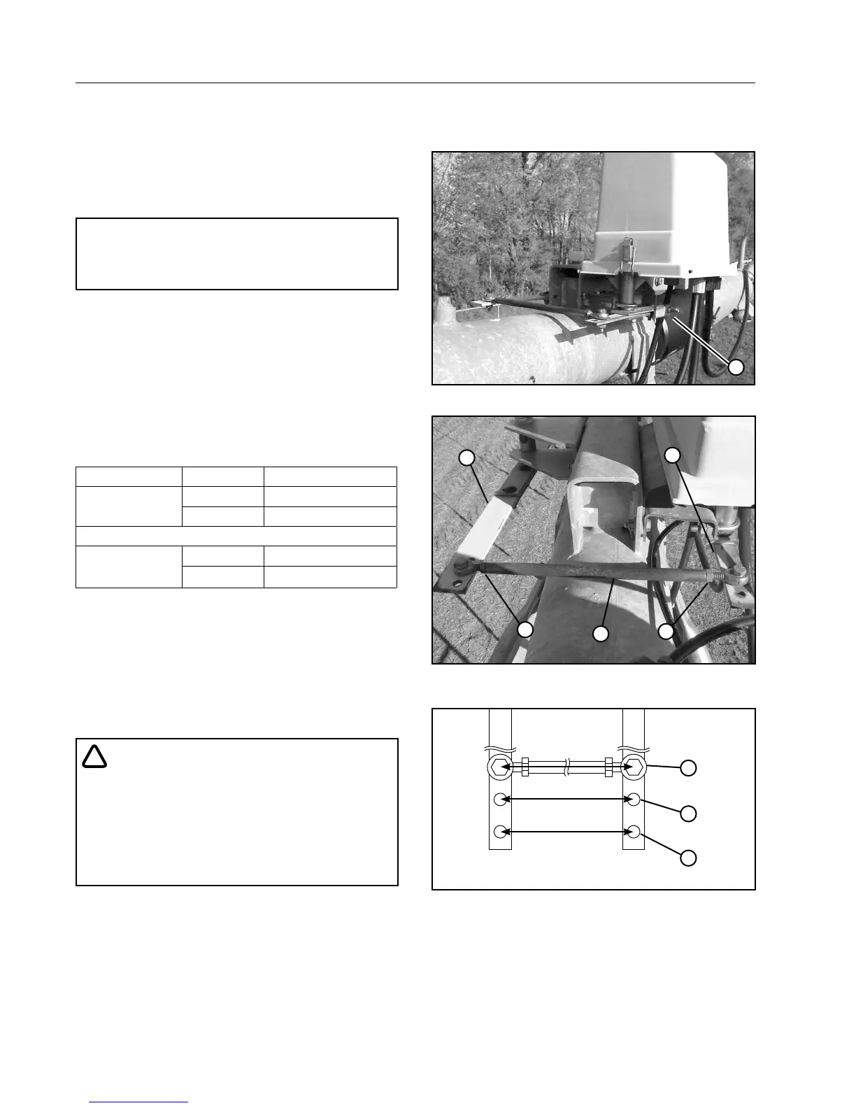
1
2
3
Figure 88-3 Connection Rod Sensitivity
1. Position 1 - Most Sensitive
2. Position 2 - Less Sensitive
3. Position 3 - Least Sensitive