5.2 Fireplace flue pull.
Close all doors and windows in the room in which the appliance is to be installed.
After confirming with a match that smoke is drawn into the flue, light a 13 gram
smoke pellet and check that there is a definite flow through the flue. Verify outside
that the smoke exits from one terminal only and that the termination is suitable.
Observe where possible, upstairs rooms and loft spaces for signs of escaping smoke
indicating a defective flue. If there is not a definite flow warm the flue for a few
minutes and repeat the smoke pellet test. If there is still no definite flow the flue may
need remedial work – Do not fit the appliance until there is a definite flow
through the flue.
5.3 Appliance preparation.
5.3.1. Stand the fire upright.
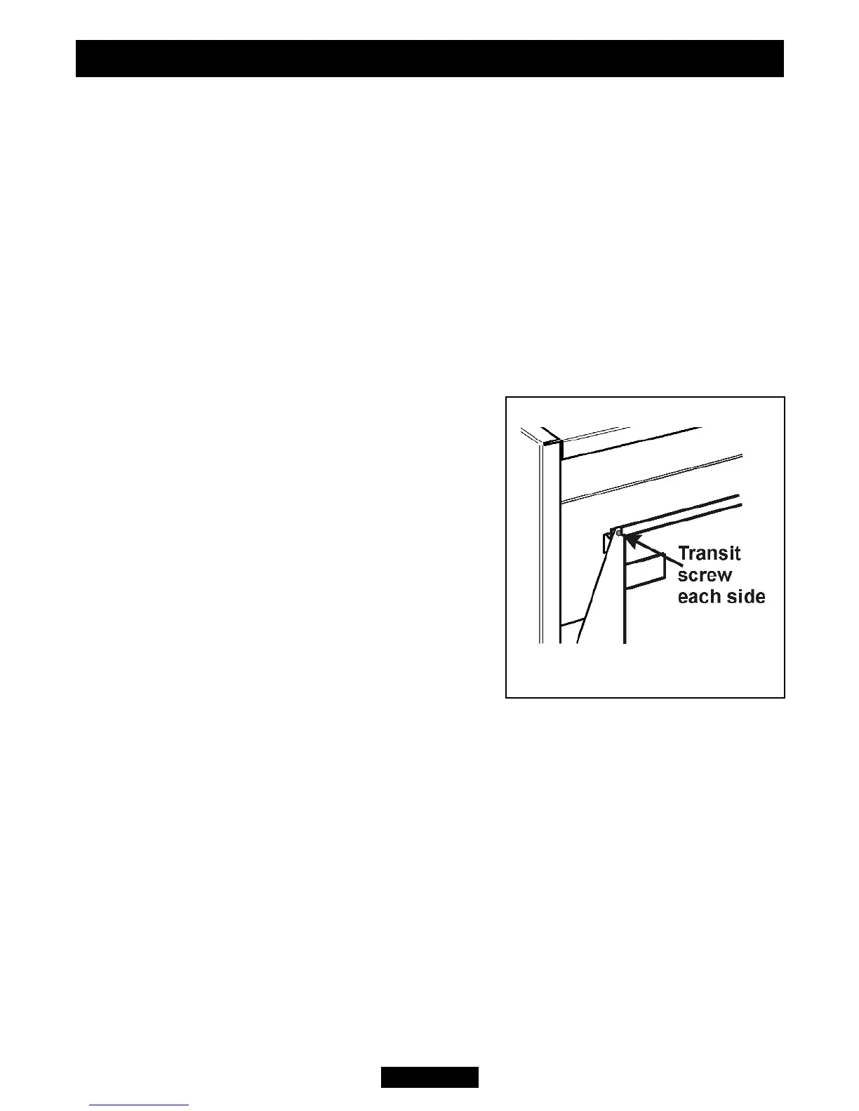
5.3.2. Remove the two transit screws from near the top of the back panel wings (See
figure 4).
5.3.3. Remove the control knob by pulling clear of
the gas tap spindle.
5.3.4. Remove the two fascia retaining screws
located at the front of the fascia near the bottom
corners.
5.3.5. Lift the fascia up and forward to clear the rear
top location. Store in a safe place.
5.3.6. Remove the radiant pack.
5.3.7. Remove any protective film from all the bright
trims.
5.3.8. If the fire is fitted to a recessed fireplace, an
extension flue spigot up to a maximum total length
of 125mm may be used. The extension must be a
tight fit over the flue spigot and be secured by two
self tapping screws. Note the minimum clearance required as shown in figure 2.
5.4 Fitting the battery to electronic ignition models.
1. At the front of the electronic spark generator there is a removable circular battery
cover. Unscrew the cover in an anticlockwise direction.
2. Remove any protective film from the battery and place into the generator. The
negative ( - ) terminal should go in first. The battery cover is marked with ( + ).
3. Screw on the cap.
5.5 Checking the ignition.
5.5.1 Manual ignition.
Before attempting to install, it is worth checking that the piezo electric spark ignition
system operates satisfactorily.
To initiate the spark, temporarily fit the control knob to the spindle. Depress the knob
and while keeping it depressed, slowly turn to the 1/IGN position. Two separate
Figure 4. Transit screws.
INSTALLER GUIDE
© Baxi Heating U.K. Limited 2008.
Page 15