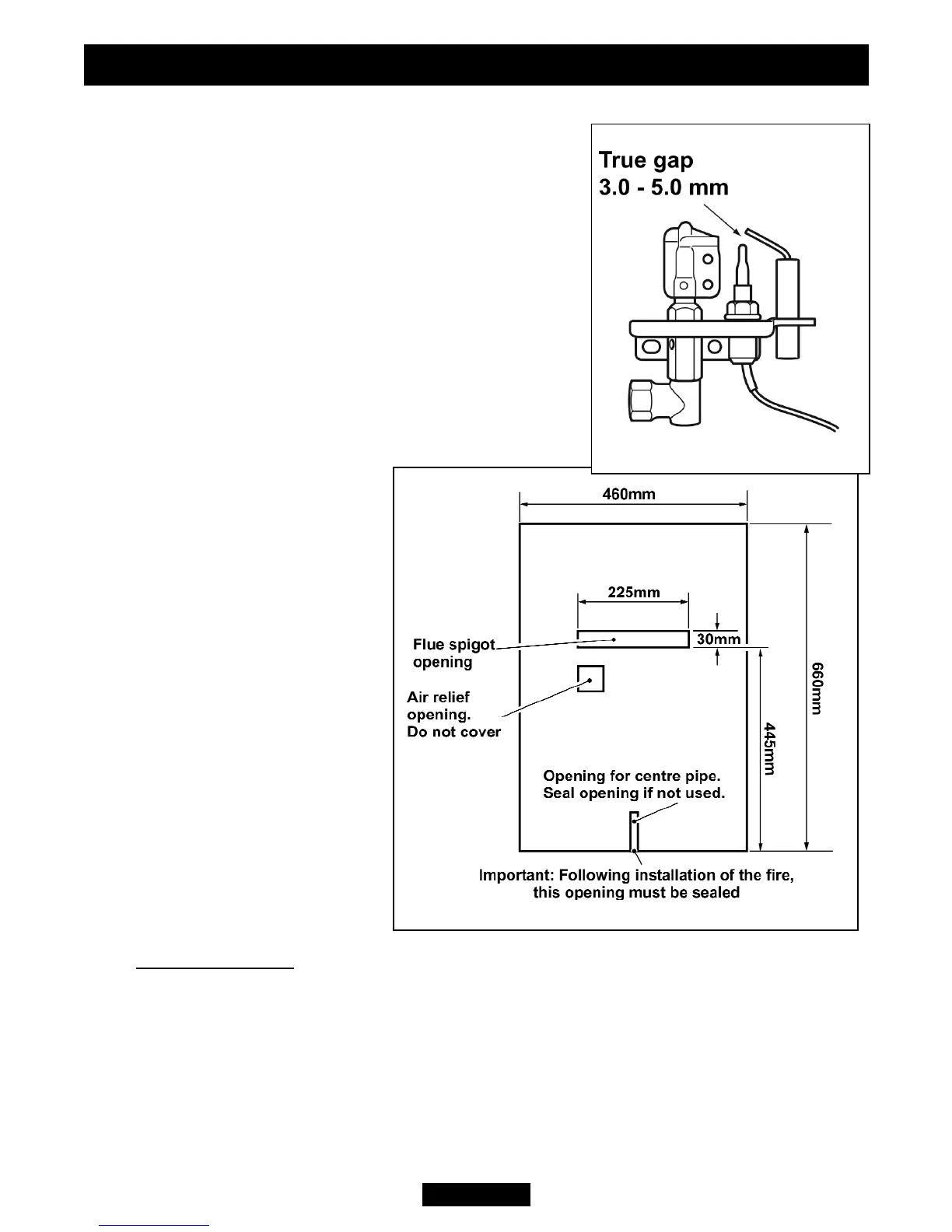
sparks should track from the electrode pin to the thermocouple tip. If there are no
sparks or incorrect tracking, check the spark gap
between the electrode wire and thermocouple tip (See
figure 5).
If the spark gap is correct, check the ignition wiring.
5.5.2 Electronic ignition.
Before attempting to install, it is worth checking that
the electronic spark ignition system operates
satisfactorily. To initiate the spark, temporarily fit the
control knob to the spindle. Apply pressure to the top of
the control knob spindle. Sparks should be generated
between the electrode and thermocouple tip on the
pilot unit. If there are no sparks or incorrect tracking,
check the spark gap between the electrode wire and
thermocouple tip (See figure 5).
If the spark gap is correct, check
the ignition wiring.
5.6 Fitting the closure plate.
The spigot opening in the closure
plate has two ‘flange’ sections.
Fold along the perforated line of
Flange 2. The dimensions of the
closure plate will be as in figure
6.
The closure plate has an
opening at the bottom for a
central gas feed pipe. The gap
between the pipe and this
opening should be sealed with
tape after connection. If a
central feed pipe is not
required the opening should
be completely sealed with
tape.
5.6.1 Hearth mounting.
(See figure 7).
The closure plate must be fitted and sealed to the hearth and fireplace opening using
a suitable heat resistant material. If necessary cut the closure plate but make sure
that it overlaps the fireplace opening sufficiently to allow satisfactory sealing. Make
sure that the square air relief opening is fully within the fireplace opening.
Figure 6. Closure plate.
INSTALLER GUIDE
Figure 5. Pilot spark gap
© Baxi Heating U.K. Limited 2008.
Page 16