6. APPLIANCE INSTALLATION
6.1 Installing to a hearth.
6.1.1 Place the fire centrally on the hearth making sure that the spigot lines up with
the spigot hole in the closure plate. Gently slide the appliance into place being
careful not to scratch the hearth. The spigot must enter the closure plate to a
depth of at least 15mm.
6.1.2 Level the fire by loosening the lock nuts and turning the leveling screws in the
feet up or down as required while they bear on the hearth. When the fire is level and
square to the wall, retighten the lock nuts.
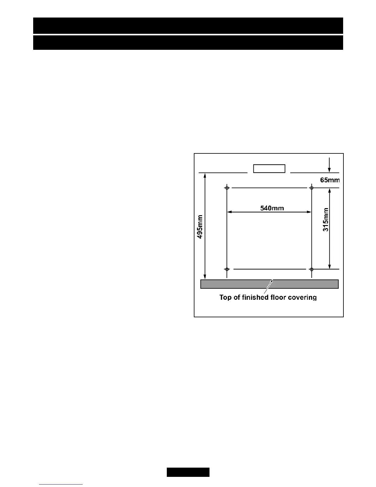
6.2 Wall mounting.
The fixing hole positions in relation to the
flue spigot opening are shown in figure 9.
Mark these positions on the wall. The
positions can alternatively be marked by
placing the fire in position and marking the
wall through the holes in the back panel.
Drill and plug the holes using a suitably
sized masonry drill bit for the wall plugs
supplied. Place the fire in position and
secure with four no.10 x 2in. wood screws.
6.3 Gas supply connection.
8mm rigid tubing must be used to connect
the gas supply to the appliance. An olive
and nut are provided for connection to the
inlet “T” connector on the appliance. The
connector can be rotated to allow
connection from either side or the rear. The connector includes a valve for isolating
the gas supply.
The closure plate has a cut-out in the base for rear connection. Seal the gap between
the cut-out and the supply pipe.
Pressure check the installation pipework for gas soundness. In the United Kingdom
check in accordance with the current edition of BS6891. In the Republic of Ireland
refer to the current edition of IS 813 “Domestic gas installations”.
6.4 Radiants installation.
Important: Fit the radiants ensuring that their rear face rests against the horizontal
ribs in the rear panel. There will be a small gap between their bottom front edges and
the retaining channel at the front of the radiant box.
INSTALLER GUIDE
Figure 9. Wall fixing holes
© Baxi Heating U.K. Limited 2008.
Page 18