within 60 seconds of the pilot going out. If the valve does not operate within this
time limit do not allow the appliance to be used until the fault has been corrected.
This monitoring system must not be adjusted, bypassed or put out of
operation.
This monitoring system, or any of its parts, must only be exchanged using
Valor Fires authorised parts.
7.3 Check reference pressure.
The appliance is pre-set to give the correct heat input at the inlet pressure shown in
section 3 of this manual. No adjustment is necessary.
7.3.1 Detach the control knob from the spindle. Remove the fascia.
7.3.2 Check the burner pressure by fitting a pressure gauge at the test point. The test
point is on the gas tap. Check the pressure with the appliance alight and set at
maximum output (Control position 5).
7.3.3 After checking, turn off the appliance. Remove the pressure gauge and replace
the test point sealing screw. Relight the appliance. Turn to the maximum output
position and test around the sealing screw for gas soundness with a suitable leak
detection fluid.
7.3.4 If all the above checks are satisfactory, continue with the installation. If not,
check the control and ignition circuitry and components as described in the servicing
section of this manual.
8. FASCIA FITTING
Before continuing with the installation of this appliance it is important that the
information contained on the back pages of the Owner guide is completed.
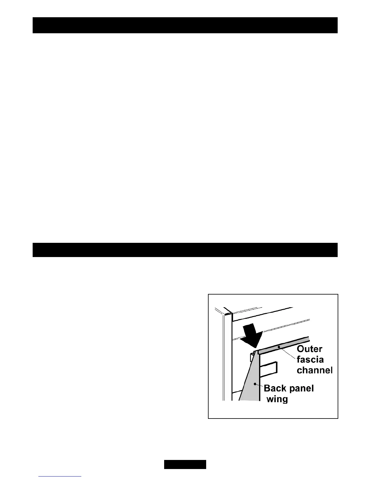
Place the fascia over the engine. Make
sure that the channel near the top of the rear of
the fascia locates fully into the wings of the
engine back panel (See figure 11).
Fit the control knob firmly on to the control
spindle.
Refit the two fascia retaining screws at the
front of the fascia near the bottom corners.
Figure 11. Fascia top location
INSTALLER GUIDE
© Baxi Heating U.K. Limited 2008.
Page 21
 Loading...