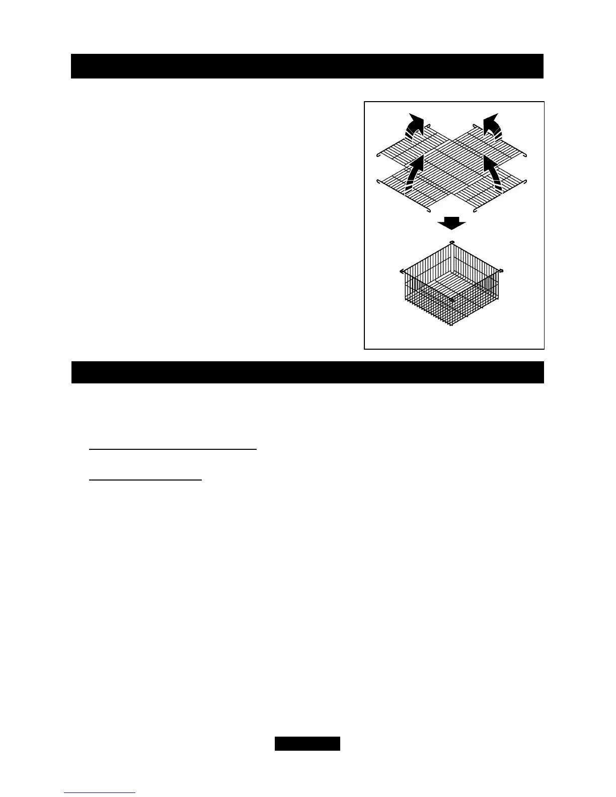
9.3 Fitting the terminal guard.
- Fold the terminal guard as shown in figure 19.
- Place the guard centrally over the flue terminal.
- Holding the guard in position and using it as a
template, mark on the wall the positions of the four
fixing holes.
- Remove the guard. Drill and plug the holes with
the four plugs supplied.
- Replace the guard and refix with four woodscrews
supplied.
10. GAS CONNECTION
Connecting the gas supply pipe.
- Complete the supply pipe connection
- For concealed rear connection
, the pipe run should have been extended as in
section 7 of this guide. Connect the inlet ‘T’ connector to the appliance inlet pipe.
- For Side Connection
, the pipe should be routed to pass through a cut-out at the
side of the casting or fascia. Where a cut-out is not provided it will be necessary to
create one. For right side connection, the pipe should also be formed to clear the
control unit. Connect the inlet ‘T’ connector to the appliance inlet pipe.
- Pressure test the installation pipework for gas soundness in accordance with the
current edition of BS 6891.
Page 29
© GDC Group Ltd. 2014
INSTALLER GUIDE
Figure 19. Terminal guard