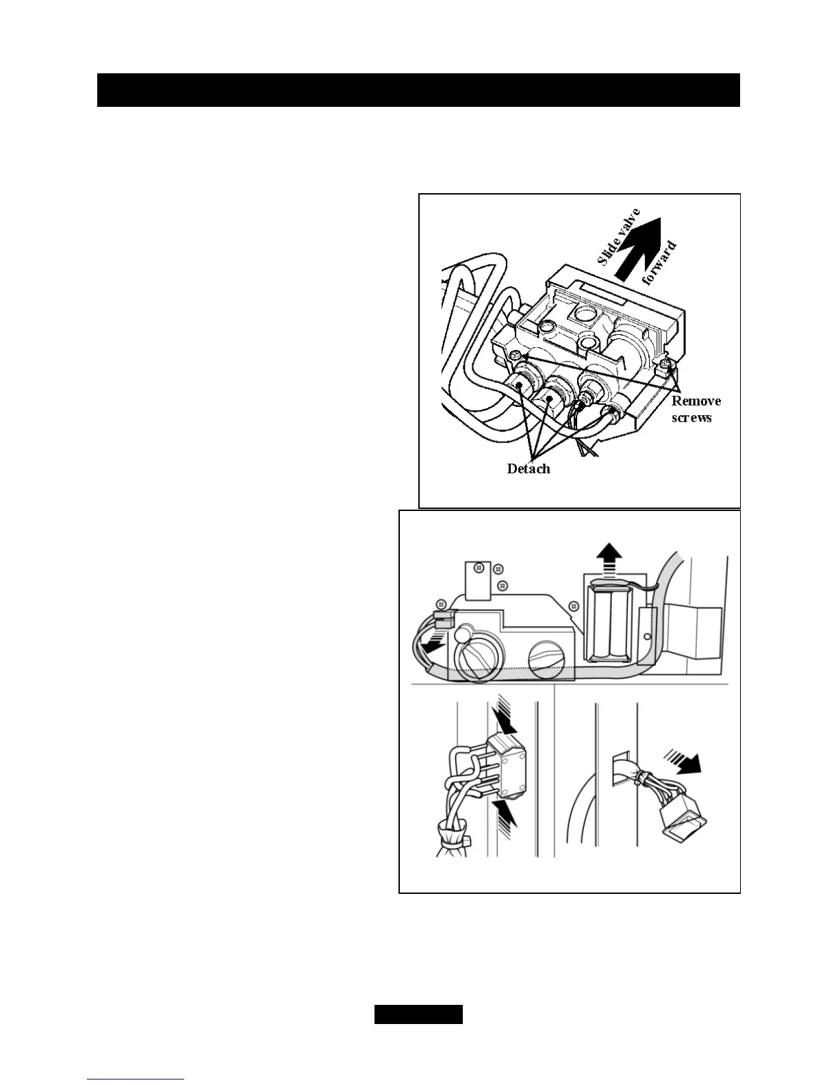
16.9 To remove the gas valve.
- Remove the complete burner module as in section 16.5
- Remove the electrode lead at the pilot. Do this by holding the lead as close to the
electrode as possible. This will limit the possibility of damaging the lead connection.
- Unscrew the thermocouple at the rear
of the gas valve.
- Undo the inlet, outlet and pilot nuts on
the gas valve.
- Remove the two mounting screws on
the underside of the gas valve (See figure
53).
- Remove the valve by sliding it forward.
- Replace in reverse order.
- When replacing, make sure that the
wiring loom runs above and to the right of
the battery box and behind the control
valve (See figure 54). The motor lead
connectors are two different sizes. They
will only fit to the correct motor terminals.
16.10 To remove the switch and
wiring loom.
(See figure 54).
- Remove the fascia (See section
16.1).
- Disconnect the two motor leads from
the top left of the gas valve.
- Cut the cable tie securing the loom
to the battery box bracket. Pull the loom
out from behind the control valve.
- Detach the two leads from the plastic
battery holder.
- Press firmly inward the two retaining
claws on the inside of the rocker switch.
Remove the loom through the switch
aperture in the case side.
- Replace in the reverse order.
- When replacing the switch make
sure that the white printing on the
switch side faces the back of the fire. If the printing faces the front, pressing the upper
half of the switch will lower the flame height.
- When replacing, make sure that the wiring loom runs above and down to the right
of the battery box and behind the control valve (See figure 55).
Page 40
© GDC Group Ltd. 2014
INSTALLER GUIDE
Figure 53. Control valve removal.
Figure 54. Switch and wiring loom removal.