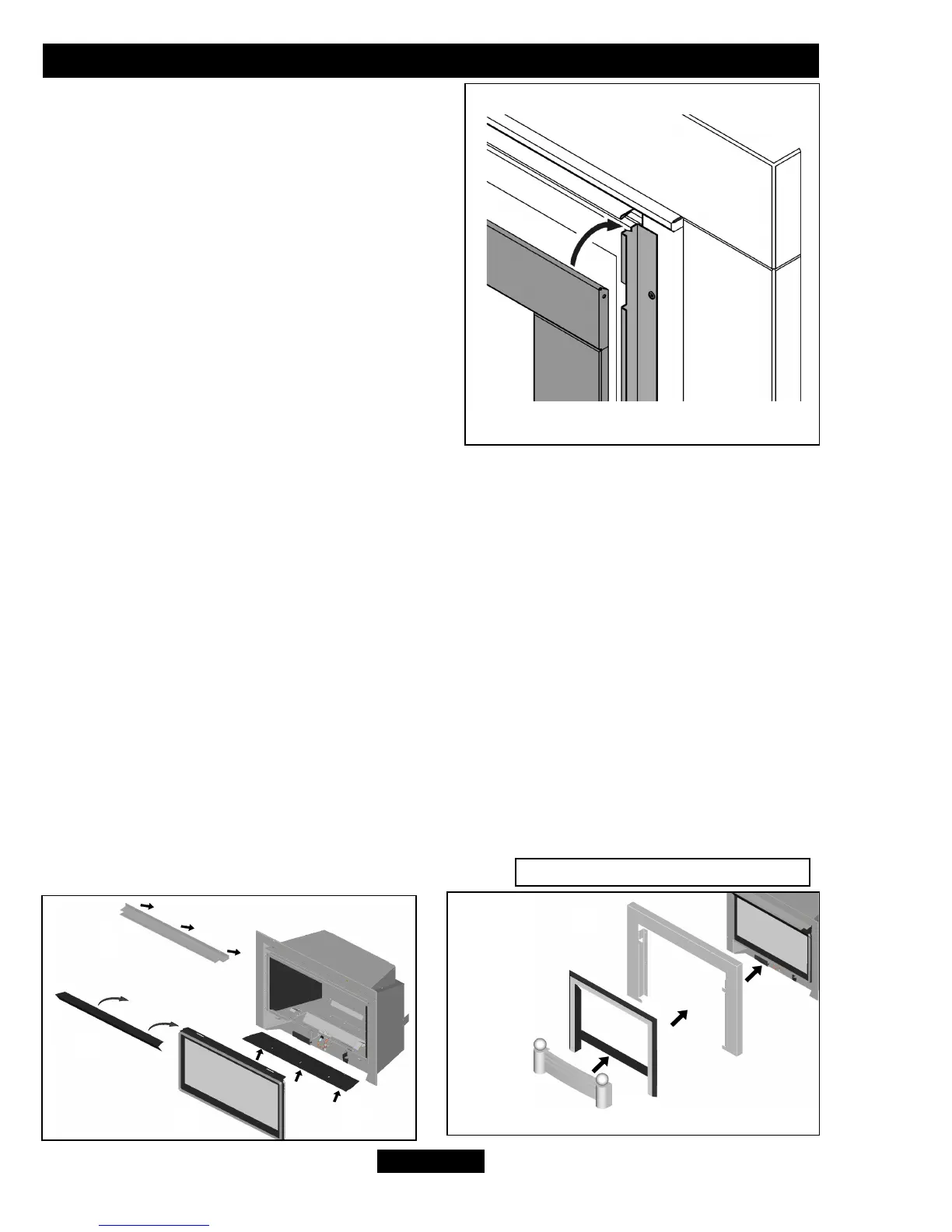
4. Keeping the lower part of the inner trim
clear of the window locate the upper edge
into the slots at the top of the window side
trims (See figure 10). The inner trim has
slots in its rear, ensure that these locate
onto the window trim. Lower the inner trim
until it is retained by the magnets at the
base of the window side trims.
5. Blakely fascia - Refer to the two illustrations
(See Fig 9) for guidance on the order in which
the fascia components are assemblied.
- Item A” Port Cover” should already be screw
fixed in place as described in 14.4
(See Fig 25, Installer Guide) inside the roof of the fire box.
- Item B “Outlet Baffle” is screw fixed using 4 screws across the top front of the
convector box, this L shaped baffle must be mounted with the screws fixed above the
horizontal flat section that protrudes out from the face of the engine.
- Item C “Window Panel” is hung onto the front of the engine and secured
(Ref. Figs 7 & 8).
- Item D “Window Cover” is then placed hanging onto the top of Item C.
- Item E “Outer Frame” is fixed using 6 screws (supplied) onto the main engine, with
Item F “Inner Frame” then secured by placing it into the outer frame Item E and
releasing it down to slot in place.
- Item G “Fret” is secured by locating the two rear screws into the locating slots in
Item F. There are two adjustable screws at the rear of the fret that can be adjusted to
ensure the fret locates securely.
© GDC Group Ltd. 2013
Page 51
OWNER GUIDE
Figure 10.
Figure 9. Blakely fascia fitting
B
F
E
G
A
D
C
 Loading...