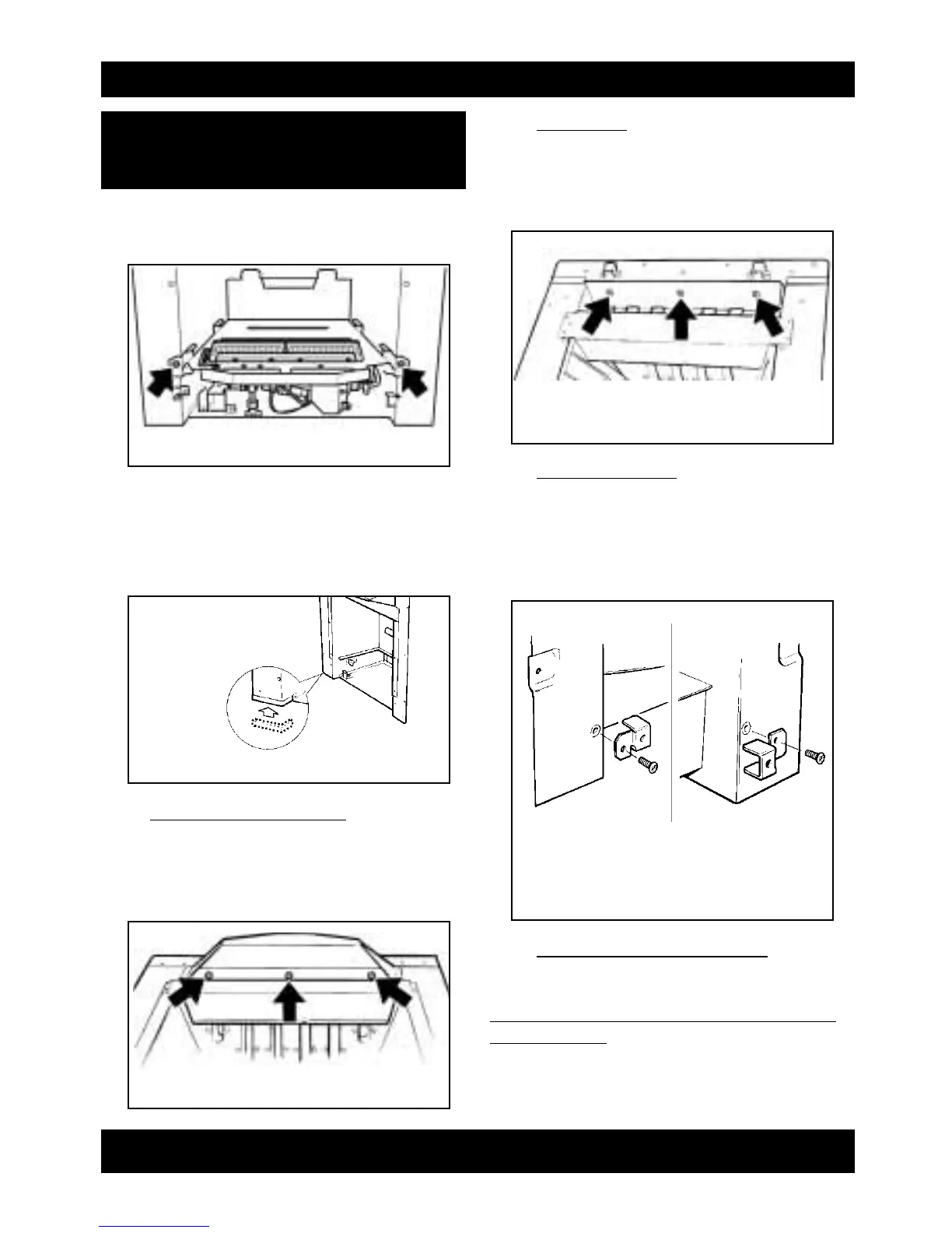
6.1 Detach the burner unit from the
convection box by removing two screws
(see figure 11). Lift the burner unit clear.
6.2 Fit the two “U” section seals to the bottom
edges of the convection box side flanges.
The seals should cover the front edges
and the side edges up to where they meet
the convection box base (see figure 12).
6.3 “Adorn” & “Visage” Fronts
Attach the canopy shield to the convection
air outlet aperture using the three tapping
screws supplied in the fire front pack (see
figure 13).
6.4 “Icon” Front
Attach the top shield to the convection air
outlet aperture using the three tapping
screws supplied in the fire front pack (see
figure 14).
6.5 “Visage” front only
Fit the two surround securing brackets to
the convection box side flanges with the
screws supplied. Note the different
orientation of the brackets at left and right
sides - See figure 15.
6.6 For Concealed Connection Only
Cut a slit in the seal at the back of the
convection box. The seal must envelop the pipe.
Do not slit the seal unless the supply pipe is to
pass through it.
Page 11
INSTALLER GUIDE
6.PREPARING THE APPLIANCE
FOR INSALLATION
figure 11 Burner attachment points
figure 12 “U” Seals
figure 13 “Adorn” & “Viasge” Canopy shield
attachmant
figure 14 “Icon” Top shield attachment
figure 15 “Visage” Surroud securing bracket
Right side
Left side
 Loading...