7.3 ALL INSTALLATIONS
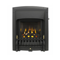
Important - Seal The Floor Front
Using
the floor sealing tape supplied, seal the
bottom of the convection box to the
fireplace and hearth floor (see figure 25).
Make sure that the whole length of the
front edge of the convection box is fully
sealed.
8.1 Refit the burner unit to the convection box
with two screws.
8.2 Connect the supply line to the appliance.
8.3 Pressure check the installation pipework
for gas soundness in accordance with
the current edition of BS6891.
8.4 Preliminary burner checks
Some burner operations can be checked
at this stage. Checking now will mean that
less disassembly will be required if any
problems are found. A full check should
still be made, however, after final
installation.
8.4.1 If closed, open the isolating valve at the
inlet elbow.
8.4.2 Rotate the control pivot bracket clockwise
as far as it will go and hold in this
position (see section 3.1.2 & figure 8).
This should close the ignition circuit and
(now that the gas is connected)
simultaneously open the gas tap allowing
the gas to flow to the pilot.
Wait a few seconds while the air is
purged. The electronically generated
sparks should light the pilot. The pilot
should then light the main burner at its
low setting. There may be a delay of up to
four seconds between the pilot lighting
and ignition of the gas at the main burner.
This is normal and is due to the time
required to fill the main burner
compartment with sufficient gas for
ignition.
8.4.3 When the burner is operating properly,
gradually turn the control pivot bracket
anti-clockwise. The burner flames should
gradually increase until the pivot bracket
is nearly at its furthest anti-clockwise
rotation. Rotating further until the pivot
bracket comes to a stop should then turn
the burner and pilot off. When the above
checks have been completed close the
isolating valve on the inlet elbow.
8.4.4 If the above checks are satisfactory,
continue with the installation. If not,
check the control and ignition circuitry
and components as described in the
servicing section of this manual.
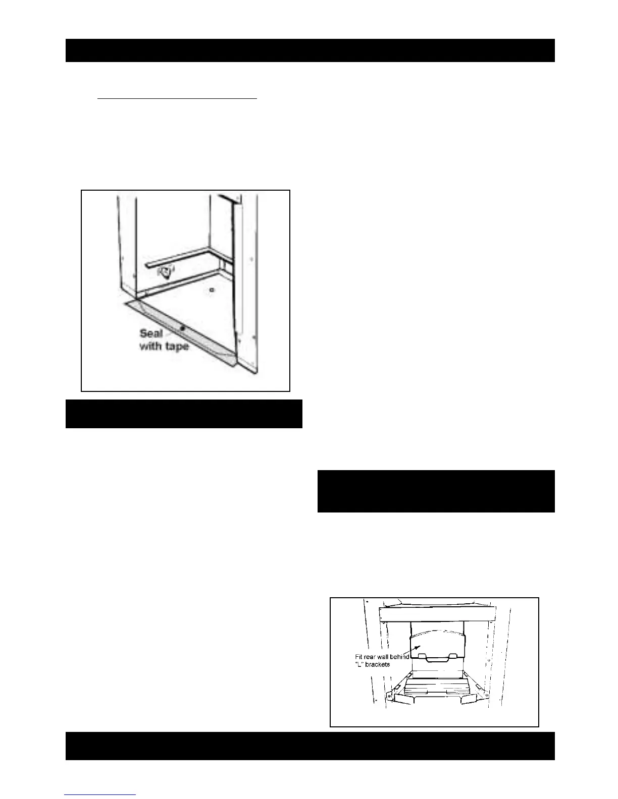
9.1 Fit the ceramic rear wall inside the “L”
brackets on the back face of the burner
compartment. Push the ceramic wall flat
against the back face of the burner
compartment (See figure 26).
Page 15
INSTALLER GUIDE
figure 25 Floor sealing
figure 26 Ceramic rear wall installation
8.BURNER INSTALLATION
9.CERAMIC WALLS
INSTALLATION
 Loading...