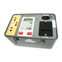
LTCA-10/LTCA-40 USER’S MANUAL
13
Table 4.0 Functional Descriptions of LTCA-40 Controls and Indicators
Item
Number
Panel Markings Functional Description
1
AC Current Clamp-on AC current probe connector
2
USB USB Interface port
3
None
The air intake cooling fans maintain the internal temperature. There are output
air fans on the sides of the case
4
120-240 7.5A, 50-60
Hz
Fuse: 250Vac, 10A
Fast-Blow
Input power connector with third-wire safety ground, ON/OFF rocker toggle
switch with built-in fuse protection
5
GROUND
5/16-18 threaded stud, with hand-turned wing nut, safety ground. This must be
connected to station ground before connecting LCTA-40 test leads to the
transformer
6
Flash Drive USB Flash Drive Interface Port
7
None
Built in 4.5-inch wide thermal printer.
NOTE: For best printing results, it is recommended that only VIC thermal paper
be used
8
None
Liquid-Crystal Display, 64 x 128 dot graphic display. Back-lit and viewable in
bright sunlight and low-light conditions. Displays menus, user selections, status
readouts and test results
9
LTC Control
Load Tap Changer Control. Allows the user to change the Load Tap Changer
position using the RAISE and LOWER buttons
10
DISCHARGE
Red LED indicator light. When lit, this indicator warns the operator that the
LTCA-40 is discharging the stored energy in the transformer.
Do not disconnect test leads when this light is on. Failure to heed this
warning can result in shock to personnel
11
HIGH VOLTAGE
PRESENT
Red LED indicator light. Lights to warn operator that there is a possibility that
voltage exists across test leads.
Do not disconnect test leads when this light is on. Failure to heed this
warning can result in shock to personnel
12
None
Membrane keypad, 10 alpha-numeric keys and 6 function keys (START, STOP,
CLEAR, ENTER, and CONTRAST/PAPER positioning UP and DOWN)
13
RS-232C
9-pin RS-232C interface port; female DB type. Data rate is set to 19,200 baud,
1 start bit, 2 stop bits, 8 data bits and no parity bit
Pin Signal
2 RX
3 TX
5 Signal Ground
14
V1, V2, V3,
CURRENT (I+, I-)
Voltage sensing input channels 1, 2, & 3. Female test connector jacks for
connecting test current output test leads
15
RAISE Fuse for LTC Control Raise leads
16
LOWER Fuse for LTC Control Lower leads
17
LTC CONTROL Load Tap Changer controller connector