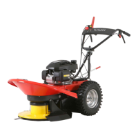
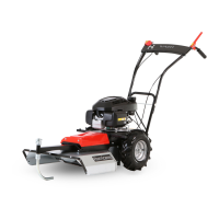
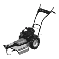
BDR-720D Adela PRO
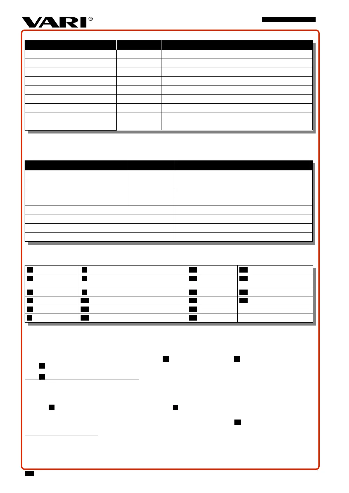
2.3.1.1 TECHNICAL DATA
Description Unit Value
Length x width x height
40
mm 1735 x 715 x 1490
Weight kg 86
The machine's maximum working width cm 70
Safe slope operation 10°
Cutting disk speed
41
min
-1
1480
Blade peripheral speed m.s
-1
54,3
Travel speed km.h
-1
1,88 - 2,76 - 3,29 - 4,57 / R: 2,58 km/h
Machine's surface power
42
m
2
.h
-1
1380 – 1933 - 2300 – 3197 / R: n/a
Gear oil / specifications l (litre) / SAE / API 0,5 / mineral gear oil 85W-90 / API GL-5
Table 17: Technical specifications
2.3.1.2 ENGINE INFORMATION
Further information about the engine not stated here is available at the engine manufacturer’s website
43
.
Description Unit Value
Engine - HONDA GCV200
Maximum (set) engine speed min
-1
3000 ± 100
Maximum (permanent) tilting of the engine
20°
Maximum (short term
44
) tilting of the engine
30°
Fuel tank capacity l (litre) 0,91
45
Fuel petrol (unleaded)
46
Oct. No. 91-95
Engine oil filling l (litre) 0,4
Oil grade SAE / API SAE 10W-30 / SJ nebo SH
Table 18: Engine Technical Information
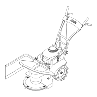
2.3.2 DESCRIPTION OF THE BASIC MACHINE PARTS
1 Cutting disc cover 7 Handlebars adjustment joint 13 Accelerator lever 19 Oil dipstick
2 Mudguard between
the wheels
8 Wing bolt for handlebars height adjustment 14 Shift lever 20 Starter handle
3 Cutting disk 9 Wing nut for handlebars horizontal adjustment 15 Left wheel 21 Sulka hinge
4 Blade (4 pcs) 10 Cutting disc drive clutch lever 16 Right wheel 22 Safety cover of the cutting disc
5 Front handle 11 Travel clutch lever 17 Tank cap
6 Handlebars holder 12 Service and parking brake lever 18 Air filter
Table 19: Legend for Fig. 1
2.3.3 MACHINE CONTROL ELEMENTS
2.3.3.1 HANDLEBARS HEIGHT AND HORIZONTAL ADJUSTMENT
• The handlebars joint enables their height adjustment
Fig.
2
B , horizontal adjustment
Fig.
2
C and tilting to the transport position
Fig.
2
F
Fig. 2
B
VERTICAL HANDLEBARS ADJUSTMENT
:
Always switch off the engine before adjusting any handlebars position! There is the risk of losing control of your
machine!
• For choosing a comfortable grip on the handlebars.
•
Fig. 2
A Loosen and completely unscrew the plastic thumbscrew 1 on the joint on the right.
• Adjust the height of the handle on the ground, so you can hold the handlebars comfortably.
• Insert the plastic thumbscrew into one of the three holes in the foot of the handle joint –
Fig.
2
D - and tighten it firmly.
40
Handlebars in the middle position for the handle height adjustment, control levers in the off position.
41
Actual speed of unloaded disc without any belt drive loss.
42
The machine’s surface power depends on the type of mowed vegetation, the stated values are only theoretical, the machine’s maximum working width is used for the calculation.
43
For more information about the engine, including the spare part numbers, visit www.honda-engines-eu.com.
44
Short term - up to one minute.
45
Measured per new standard Society of Automotive Engineers (SAE) J1349.
46
With regard to the ever increasing ratio of BIO-components in fuel, use fuel stabilizer.
26