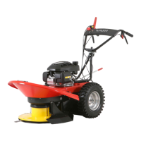
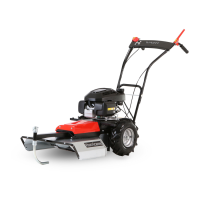
BDR-720D Adela PRO
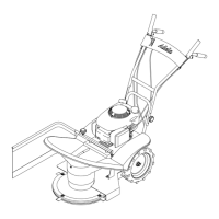
Handlebars fitting >2 a nd >3
4) >2 Remove the screw connection of the handlebar joint 6 : screw M8x30 7 and self-locking nut M8 8 - 2x spanner No. 13.
5) >3 Turn the handlebars 180° to the right. None of the bowden cables may pass out between the feet of the handlebars! Insert
the handlebar joint web 6 between the handlebar tube tube feet. Insert the M8x30 screw 7 into the lower hole in the foot
and into the middle hole in the joint. Screw in the self-locking nut M8 8 . Tighten the joint only so that the handlebars can only
be moved with slight resistance.
6) >3 Apply a little grease, Vaseline spray or engine oil 9 to the thread end of the plastic thumbscrew. Screw the screw into one
of the three selectable handlebar height positions and tighten it firmly.
Bowden cable mounting >4
7) Attach the travel clutch bowden cable 10 from the lower right lever with the cable tie 11 , inserted into the hole in the right
handlebar holder. The bowden cable must be on the inside of the pipe and should follow the smoothest possible arc with the
largest possible radius.
8) Attach the service and parking brake bowden cable 12 from the lower left lever and the throttle bowden cable 13 with a
common cable tie 14 , inserted into the hole in the left handlebar holder. Align the two bowden cables, so that they are on
the inside of the pipe and so that the bowden cables follow the smoothest possible arc with the largest possible radius.
Shift lever Installation and Adjustment >5 a nd >6
9) Sort the fasteners from the package of parts: 1x A 1x B on
Fig.
26
10) >4 Place the shift lever 15 on the transmission square. Screw the M6x16 screw 16 together with the flat washer 17 into the
square thread - do not tighten it, for the time being. Between the arrow and foot on the handlebar holder plate, there insert the
flat washer 17 . Insert the M6x16 16 screw into the hole in the arrow and the foot on the handlebar holder plate 16 , screw in
the M6 self-locking nut 18 . Tighten them, so that the screw connection has a very small play - 2x spanner No.10.
11) >5
Move the shift lever a few times back and forth between gear 4 and reverse gear ”R”. Return the shift lever to neutral ”N”
and centre the arrow against the point indicating the gear engaged. Now, very strongly tighten the screw 16 on the shift lever
foot 15 - 1x spanner No. 10. Check that the arrow points correctly to all the gears, adjust the deviation by adjusting the position
again.
Cutting Disc Cover Installation >7
12) Sort the fasteners from the package of parts: 6x C 2x D 2x E on
Fig.
26
13) >7 Slide the cutting disc cover 3 from the front as far as it will go to the mudguards. Then lift the rear part slightly and slide
both vertical parts of the cover moulding behind the feet of the fenders 19 .
14) Using the connection C - 4x connect the cover 3 on both fenders 19 and using the connection C - 2x in the area under the
engine. The washer must always be between the screw head and plastic cover. Do not tighten yet.
15) Place the front handle on the cover 20 . Using the connections D - 2x and E - 2x connect the handle to the cover. Do not
tighten yet.
16) Now, gradually tighten the joints in this order: 4x C on the fenders, 2x C under the engine, 2x D , 2x E - all the joints 2x
spanner No. 10.
2.8 DEVICE TRANSPORT
When transporting the machine in a car or other road vehicle, always secure the machine against any unexpected
movement with certified lashing straps.
• Flip and lock the handlebars in the transport and parking position - see
2.3.3.1.
• Insert the blades inside the cutting disc.
• The machine must always be mounted with its front part (= cutting disc) in the direction or across the direction of travel of the vehicle.
• The lashing points are (straps are shown by thick lines on
Fig.
2
F ):
➔ in the rear part of the machine a tubular bumper or behind the foot of the hinge for the Sulka
➔ in the front of the machine the cutting disc cover
• Brake the machine with its parking brake - see
2.3.3.5
on page
28.
2.9 STORAGE
• Prior to any long-term storage (e.g. at the season end) remove all the dirt and plant residues from the machine.
• Prevent unauthorized persons from access to the machine.
• Protect the machine against climatic conditions but do not use impermeable protection to prevent excessive corrosion it may cause.
We strongly recommend the following steps:
➔ Check the integrity of the working blades - sharpen the blade edges or turn the blades over
60
; preserve the blades
In case of any major damage to the blades, replace all the four blades (incl. their complete screw connection).
➔ Remove all the dirt and plant residues from the machine
➔ Repair any paint damage
➔ Drain the fuel from the engine fuel tank and carburettor - instructions in the engine operating instructions
➔ Perform the post-season machine lubrication according to the
Table 23
➔ Check the tyre pressure and inflate the tyres to MAX
60
The blades have two edges - they may be rotated as needed. In any case, the blade must be undamaged.
36