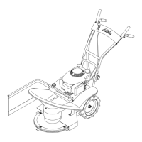
BDR-720D Adela PRO
Fig. 1: Main Machine Components Fig. 2: Handlebars height and horizontal adjustment
- Parking and transport position of the handlebars
- Fixing points when transporting the machine
Fig. 3: Accelerator lever position
1 STOP position
The engine is not running.
• Engine switch-off.
• Engine shutdown.
• Refuelling.
• Machine transport.
3 „Rabbit“ position MAX
The engine runs at its maximum speed.
• Working position
2 “Turtle” position MIN
The engine runs at its idle speed.
• Short break.
4 Position CHOKE
The engine choke is engaged.
• Cold engine start.
Fig. 4: Control elements Fig. 5: Safety pictogram - Combined sticker
Fig. 6: Safety pictogram – Disc spinning
- Position on the machine
Fig. 7: Safety pictogram – Machine travel
- Position on the machine
Fig. 8 :Safety pictogram - Service and parking brake
- Position on the machine
Fig. 9: Safety pictogram - Direction of rotation arrow
- Position on the machine
Fig. 10: Safety pictogram - Dangerous area Fig. 11: Machine Working Width
Fig. 12: Connection of the Sulka AV-650 Fig. 13: Lubrication points - bowden cables
Fig. 14: Lubrication points - pins Fig. 15: Lubrication points - pin
Fig. 16: Lubrication points - bowden cable divider
Fig. 17: Lubrication points - transmission
inspection hole plug
Oil dipstick inserting Oil level
Fig. 18: Moving blade assembly 1 Mowing blade
2 Screw
3 Nut
4 Washer
5 Rubber ring
6 Upper disc
7 Lower disc
Fig. 19: The route of the belts and their
guide elements
1 Wheel travel V-belt
2 Engine pulley
3 Transmission pulley
4 Wheel travel tensioning pulley
5 Cutting disc drive V-belt
6 Cutting disc pulley
7 Cutting disc drive tensioning pulley
8 Guide element
Fig. 20: Wheel travel pulley adjusting screw;
lubrication point
Fig. 21: Wheel travel pulley adjusting screw Fig. 22: Cutting disc pulley adjusting
element
Fig. 23: Cutting disc automatic brake
adjusting screw; lubrication point
Fig. 24: Brake pad pressure adjustment nut Fig. 25: Service and parking brake adjusting
screw
Fig. 26: Machine Assembly Procedure
Fig. 27: Tools and accessories - not part of
the machine
Spark plug spanner 21 mm (3/8“)
Ratchet handle 3/8“
VARI canister Ord. No. 3562
HONDA fuel stabiliser Ord. No. 08CXZ-FSC-250
Briggs & Stratton Fuel Fit™ fuel stabilizer (Ordering No. 992381)
Hour meter VARI POWERMETER Ord. No. 4227
Set of spare blades Ord. No. 1005900200 - use only 4 pcs of this set
Table 27: Figure caption translations
38