1. Identify flange type according the fabrication number on the identification plate; see
chapter «1.1 Identification of product».
Example: 110 . . – P . . . / . . . = Flange type ISO-F
Maximum screw-in depth «X» in mm
C = CF-F, metric thread
U = CF-F, UNF thread
Table 4-1
2. Remove protective covers from body flanges.
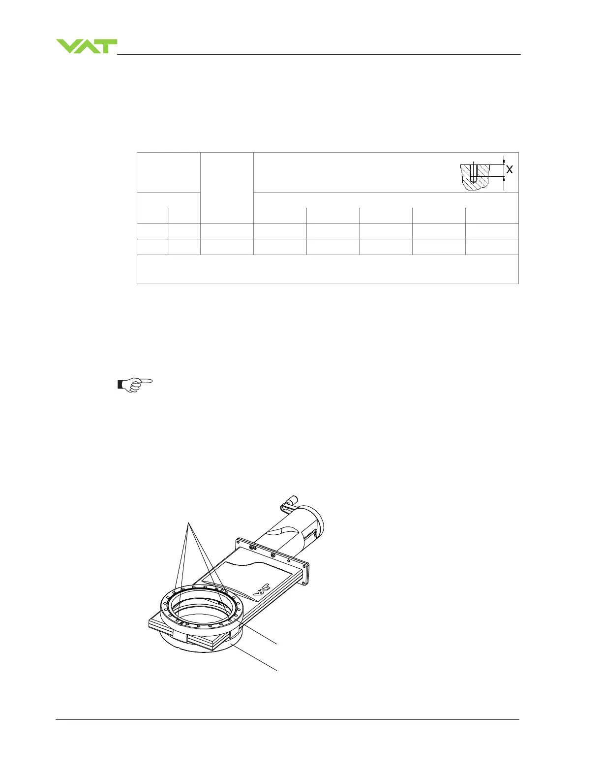
3. Clean sealing surfaces and seals of both flanges;
see (1) and (2) according to «Figure 4-1» on page 10.
The valve seat side is marked with the symbol «» on flange «A».
4. Put valve to the mounting position.
5. Mount the four screws (3) according to «Figure 4-1» on page 10, evenly in crosswise
order until the seal touches the sealing surface.
6. Tighten all screws with the torques appropriate for their property classes.
1 Flange A
2 Flange B
3 Screws
Figure 4-1
 Loading...


