EasyManua.ls Logo

VAT Series 651 - User Manual

VAT Series 651
53 pages
Print Icon
To Next Page IconTo Next Page
Loading...
Installation, Operating & Maintenance Instructions
Series 651 DN 320-400 (I.D. 12“ - 16”), Logic
VAT Vakuumventile AG, CH-9469 Haag, Switzerland
Tel +41 81 771 61 61 Fax +41 81 771 48 30 CH@vatvalve.com www.vatvalve.com
267736ED
2008-02-26
1/53
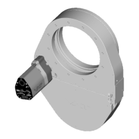
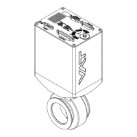
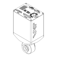
Pendulum control & isolation valve
with extended control range
with Logic interface
This manual is valid for the valve ordering number(s):
651 . . - . . GC - . . . . (1 sensor input)
651 . . - . . GE - . . . . (2 sensor inputs)
651 . . - . . AC - . . . . (1 sensor input / ±15V SPS)
651 . . - . . AE - . . . . (2 sensor inputs / ±15V SPS)
651 . . - . . HC - . . . . (1 sensor input / PFO)
651 . . - . . HE - . . . . (2 sensor inputs / PFO)
651 . . - . . CC - . . . . (1 sensor input / ±15V SPS / PFO)
651 . . - . . CE - . . . . (2 sensor inputs / ±15V SPS / PFO)
SPS = Sensor Power Supply PFO = Power Failure Option
configured with firmware 651P.1E.05
The fabrication number is indicated on each product as per the label
below (or similar):
made in Switzerland
Fabrication No.:
patented
. .
651
. .
. . . .
. . . . / . . . .
A
. . . . . .
Fabrication number
sample picture
Explanation of symbols:
Read declaration carefully before you start any other
action!
Keep body parts and objects away from the valve
opening!
Attention!
Hot surfaces; do not touch!
Product is in conformity with EC guidelines,
if applicable!
Loaded springs and/or air cushions are potential
hazards!
Disconnect electrical power and compressed air
lines. Do not touch parts under voltage!
Wear gloves!
Read these «Installation, Operating & Maintenance Instructions» and the enclosed «General
Safety Instructions» carefully before you start any other action!

Questions and Answers

  • E
    evelezAug 19, 2025
    Why does remote operation not work on my VAT 651 Control Systems?
    • J
      Jane YuAug 19, 2025
      If the remote operation of your VAT Control System is not working, first ensure that local operation via the service port is not active and that the safety mode is not engaged (check for 'D' on the display). If so, switch to remote operation. Also, ensure that the motor is receiving power. Consult the 'Electrical connection' section for detailed instructions.
  • D
    dmillerAug 21, 2025
    What to do if VAT Control Systems display shows «D C» or «D999»?
    • Y
      ymortonAug 22, 2025
      If your VAT Control System displays 'D C' or 'D999', it indicates that the motor interlock is open. To resolve this, ensure that the motor is receiving power to allow operation. Refer to the 'Electrical connection' section for detailed instructions.
  • D
    dmcmahonAug 23, 2025
    What does «SR» mean on the display of VAT 651 and how to fix it?
    • Y
      yadamsAug 25, 2025
      If the display of your VAT Control System shows 'SR' (Service Request), it could be due to heavy contamination of the valve unit or a gate seal that is heavily sticking. To address this, clean the valve and/or replace the gate seal, following the procedures outlined in the 'Maintenance procedures' section.
  • M
    Misty ThomasAug 26, 2025
    What to do if VAT 651 Control Systems display shows «E 22»?
    • S
      Scott PowersAug 26, 2025
      If your VAT Control System displays 'E 22', it indicates that the rotation angle of the valve plate is limited during operation. This is likely due to a mechanical obstruction of the valve plate. Identify and remove the obstruction to resolve the issue.
  • L
    Laura DiazAug 27, 2025
    How to fix VAT 651 when CLOSE VALVE does not work?
    • J
      Justin MartinAug 28, 2025
      If your VAT Control System is not closing, and the safety mode is active (indicated by 'D' on the display) or maintenance mode is active, ensure that the motor is receiving power to allow operation. Also, refer to the 'Electrical connection' section for details and check “Display shows «M C»” in this table.
  • M
    Melissa EnglishAug 29, 2025
    How to troubleshoot VAT 651 when OPEN VALVE does not work?
    • D
      David MillerAug 29, 2025
      If your VAT Control System is not opening, and the safety mode is active (indicated by 'D' on the display) or maintenance mode is active, ensure that the motor is receiving power to allow operation. Also, refer to the 'Electrical connection' section for details and check “Display shows «M100»” in this table.
  • M
    Mr. Jason RayAug 31, 2025
    What to do if POSITION CONTROL does not work on VAT 651 Control Systems?
    • G
      Gregory DeleonSep 1, 2025
      If the position control is not working on your VAT Control System, and the safety mode is active (indicated by 'D' on the display), ensure that the motor is receiving power to allow operation. Additionally, if 'POSITION CONTROL' is selected, indicated by 'V' on the display, select the 'POSITION CONTROL' mode. Refer to the 'Position control' section for detailed instructions.
  • S
    sabrina70Sep 2, 2025
    What does «E 40» mean on VAT Control Systems display?
    • J
      Jerry MorrisSep 2, 2025
      If your VAT Control System displays 'E 40', it indicates a fatal error related to motor driver failure. To resolve this, replace the control unit following the procedures outlined in the 'Maintenance procedures' section.
  • D
    Daniel StoneSep 4, 2025
    Why is there a COMPRESSED AIR FAILURE in my VAT 651?
    • P
      Peter HarperSep 5, 2025
      If you are experiencing a compressed air failure with your VAT Control System, it is likely due to insufficient air pressure at the air input of the valve. Connect an air supply or increase the air pressure, ensuring it exceeds 4 bar (55 psi).
  • J
    Johnny ContrerasSep 6, 2025
    Why is the pressure reading wrong or negative on my VAT 651 Control Systems?
    • C
      cranepennySep 7, 2025
      If the pressure reading on your VAT Control System is incorrect or negative, verify the following: Ensure the sensor(s) are properly connected, confirm if a 2-sensor version is present at the valve controller by checking the valve version, and verify the configuration. Perform 'ZERO' after base pressure is reached. Also, check that the sensor power supply provides adequate power. Refer to 'Electrical connection', 'Setup procedure', and 'ZERO' sections for detailed instructions.

Summary

Explanation of Symbols

1 Use of product

1.1 Technical data

Provides detailed specifications for control and actuating unit and valve unit.

2 Installation

2.1 Unpacking

Instructions for safely removing the valve from its packaging.

2.2 Installation into the system

Details on physically mounting the valve and connecting utilities.

2.3 Tightening torque

Specifies torque values for flange mounting screws to ensure proper sealing.

2.4 Admissible forces

Limits for forces applied to the valve body to prevent deformation.

2.5 Sensor connection requirements

Guidelines for optimal sensor response time and connection integrity.

2.6 Electrical connection

Covers power supply and sensor signal wiring for various valve configurations.

2.6.1 Sensor supply concepts

Explains different methods for powering connected sensors.

2.6.2 Power and sensor connection (+24 VDC sensors)

Wiring diagram for +24 VDC sensors using the POWER connector.

2.6.4 Power and sensor connection (±15 VDC sensors) with optional SPS module

Wiring for ±15 VDC sensors with the optional SPS module.

2.6.5 Logic interface connection

Instructions for connecting the valve's logic interface for remote control.

2.6.6 Service port connection

Details on connecting a computer via the service port for configuration.

3 Operation

3.1 Introduction

Overview of valve's intended use in vacuum chambers.

3.1.1 Local operation

How to operate the valve using a computer or Service Box.

3.1.2 Remote operation

How to control the valve remotely via its logic interface.

3.1.3 Safety mode

Describes the valve's behavior and status when in safety mode.

3.2 Operation under increased temperature

Specifies operating conditions at elevated temperatures.

3.3 Behavior during power up

Explains how the valve responds when power is applied.

3.4 Behavior in case of power failure

Outlines valve actions during power interruptions, with and without PFO.

3.5 Display information

Details the valve's 4-digit display for status and configuration.

Errors

Lists error codes and their potential causes and troubleshooting actions.

3.6 Setup procedure

Step-by-step guide to configure the valve for pressure or position control.

3.6.1 Interface configuration

Customizing digital inputs and LEARN range settings.

3.6.2 Valve and sensor configuration

Setting valve behavior and configuring sensor inputs.

3.6.3 ZERO

Procedure for compensating sensor offset voltage for accurate zero reading.

3.6.4 LEARN

Adapting the PID controller to system characteristics for optimal control.

3.7 Close valve

How to command the valve to close locally or remotely.

3.8 Open valve

How to command the valve to open locally or remotely.

3.9 Position control

Direct control of valve position using setpoints.

3.10 Pressure control

Configuring and tuning the valve for downstream pressure regulation.

3.10.1 Operation with 2 sensors

Details on using dual sensors for pressure measurement and control.

3.10.2 Tuning of control performance

Procedures for optimizing PID controller settings like gain and delay.

3.11 Logic interface

Explains the functions and wiring of the digital and analog interface.

3.11.1 Functions and Wiring

Detailed diagrams and descriptions of interface signals and connections.

3.11.2 Digital inputs

Lists and describes the functions of all digital input pins.

3.11.3 Digital outputs

Lists and describes the functions of all digital output pins.

3.11.4 Analog inputs and outputs

Details the use of analog signals for setpoints and feedback.

4 Trouble shooting

5 Maintenance & repairs

5.1 Maintenance procedures

Step-by-step instructions for seal replacement and valve cleaning.

5.2 Option board

Information on optional modules like SPS and PFO.

5.2.1 Durability of power fail battery

Graphical data on the expected lifetime of the PFO option board battery.

5.2.2 Retrofit; replacement procedure

Steps for replacing or retrofitting electronic boards in the control unit.

6 Drawing

7 Spare parts

7.1 Control unit

Identifies spare parts for the valve's control unit.

7.2 Valve unit

Lists spare parts for the valve body, seals, and pendulum plate.

7.3 Accessories

Details available accessories like power supplies and software.

7.3.1 Centering ring with Viton o-ring

Part numbers for specific centering rings used in ISO-F installations.

8 Warranty

VAT Series 651 Specifications

General IconGeneral
BrandVAT
ModelSeries 651
CategoryControl Systems
LanguageEnglish

Related product manuals