Console Installation Wiring the Console
5
Wiring the Console
1. Check the Input Power Rating on the label affixed to the underside of the console to verify whether input
power requirements are 120 Vac or 240 Vac.
2. Pull three #14 AWG or larger color-coded wires for AC line (hot), AC neutral and chassis ground between the
power panel and the console.
3. Pull one wire, with a minimum 90°C rating, for barrier ground - For UL/cUL installations use a # 12 AWG wire;
For ATEX/IECEx installations use a 4 mm
2
wire.
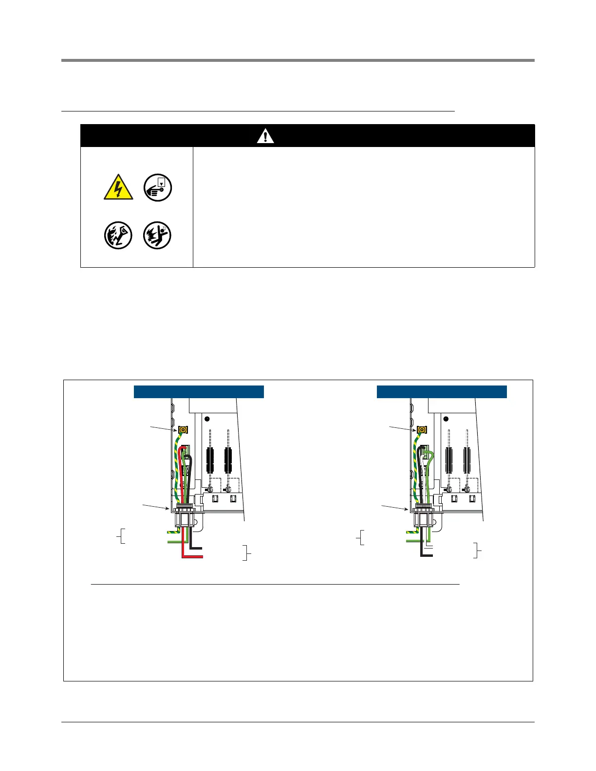
4. Connect the input 120 or 240 Vac power wires as shown in Figure 2.
Figure 2. Wiring AC Power To The TLS-450/TLS-450PLUS Consoles
WARNING
This console contains high voltages which can be lethal. It is also connected
to low power devices that must be kept intrinsically safe.
1. Do not connect the console AC power supply wires at the breaker until
all devices are installed.
2. Attach conduit from the power panel to the console's Power Area
knockouts only.
Connecting power wires to a live circuit can cause electrical shock that may
result in serious injury or death.
Routing conduit for power wires into the intrinsically safe compartment can
result in fire or explosion resulting in serious injury or death.
L1
N
L2
L1
G
L2
(To 240 Vac
breaker in
power panel)
240 Vac Power Input 120 Vac Power Input
L1 (BLK)
N/L2 (WHT)
N/L2 (BLK)
G (GRN)
Barrier (G/Y)
L1 (RED)
(To 120 Vac
breaker in
power panel)
Attach barrier wire
to grounding clamp
Power connector
conduit entry
• Barrier ground wire requirements:
- For UL/cUL approved systems, use a 12 AWG barrier ground wire
- For ATEX/IECEx approved systems, use a 4 sq. mm barrier ground wire
• Use an ohmmeter to check the electrical resistance between the console’s metal case and the power panel’s earthing
ground wire connection at the ‘known good ground’. It should read less than 1 ohm.
• Connect the power supply wires in the power panel to a separate dedicated circuit.
• Electrical rating of power input - 120 or 240 Vac, 50/60 Hz, 2 A maximum.
• See Figure 1 for locations of power conduit knockouts into the console. Power wiring must enter the console
through designated knockouts.
POWER WIRING NOTES:
To grounding
terminal bar
in power panel
G (GRN)
Barrier (G/Y)
To grounding
terminal bar
in power panel
Attach barrier wire
to grounding clamp
Power connector
conduit entry