28
5Connectingtopowersupply
MINITRAC 31 • Foundation Fieldbus
41782-EN-211203
Thecontactisthennolongersuitableforswitchinglow-voltage
circuits.
Inductive loads also result from the connection to a PLC input or
outputand/orincombinationwithlongcables.Itisimperativethatyou
take measures to extinguish sparks to protect the relay contact (e.g. Z
diode)orthetransistoror8/16mAoutput.
Instruments with intrinsically safe signal output
Youcannddetailedinformationontheexplosion-protectedversions
(Ex-ia,Ex-d)intheEx-specicsafetyinstructions.Thesesafety
instructionsarepartofthescopeofdeliveryandcomewiththeEx-
approved instruments.
8
9
2
1
7
5
3
4
6
1
1
24
/L
/N
PE
56
22
11
12
2122 1920 18 17 14 1316 15 12
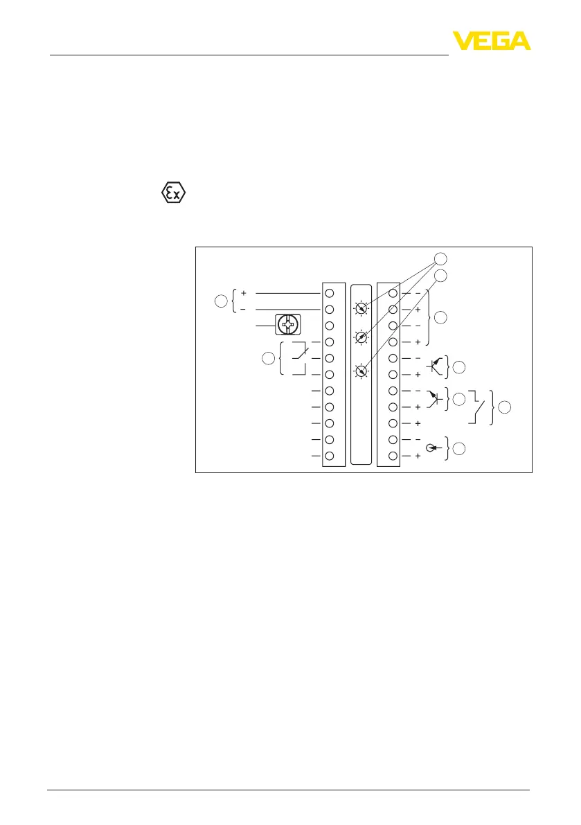
Fig. 17: Electronics and connection compartment (Ex-d) with instruments with
intrinsically safe signal output
1 Voltage supply
2 Relay output
3 Signal input 4 … 20 mA (active sensor)
4 Switching input for NPN transistor
5 Switchinginputoating
6 Transistor output
7 Interface for sensor-sensor communication (MGC)
8 Simulation switch (1 = simulation on)
9 Setting the bus address for sensor-sensor communication (MGC)
4)
Electronics and connec-
tion compartment - In-
struments with intrinsi-
cally safe signal output
4)
MGC = Multi Gauge Communication

 Loading...


