J
Mtr 1&2
No
Function
setjA
Mtr
1
setJA
Mtr
2
NOTE:
Pin 5 removed
Primary/Secondary Speeds
( Input 2 )
To VXM Auxiliary I/O
+
( Input 3 )
(Mtrs 3,4)
+
J
1
2
Mtr 1&2
Mtr 3&4
VXM1
Auxiliary I/O
VXM2
Auxiliary I/O
(Mtrs 1,2)
setjA
Mtrs
1,3
setJA
Mtrs
2,4
NOTE:
Special Velmex “Y” cable for
connecting to two VXM
controllers
Primary/Secondary Speeds
( Input 2 )
+
( Input 3 )
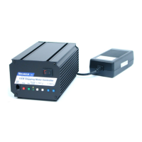
Analog Joystick with One VXM
The optional analog joystick can be used with a single VXM control.
The joystick provides analog outputs for two VXM controls. With a single VXM one output
is not connected resulting in “no function” in the one direction of the joystick.
The analog joystick has a button switch connected to Input 2 for toggling between the
primary and secondary settable jog speeds.
There is also a second button switch connected to Input 3 for alternating between motors
1 and 2.
NOTE: The default primary and secondary speeds are by default both set to 0 (disabled
joystick.)
NOTE: It is possible to disable/remove the button switch(es) if Input 2 and Input 3 are
needed for another function. To disable/remove the button(s), with the button in the out
position, use pliers to pull the button cap off the switch actuator. The switch actuator
should now be below the surface enough to prevent unintended input. An alternate
method to disable the button switches is by clipping off pin 6 and pin 7 on the cables
connector.
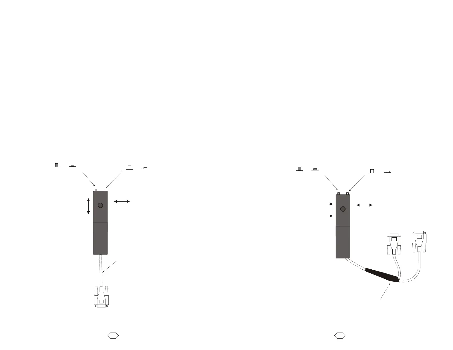
Analog Joystick with Two VXMs
The joystick provides analog outputs for two VXM controls. A connection to each VXM is
accomplished with a special Velmex “Y” cable.
The analog joystick has a button switch connected to Input 2 for toggling between the
primary and secondary settable jog speeds.
There is also a second button switch connected to Input 3 for alternating between motors
1,3 and 2,4.
NOTE: The default primary and secondary speeds are by default both set to 0 (disabled
joystick.)
NOTE: It is possible to disable/remove the button switch(es) if Input 2 and Input 3 are
needed for another function. To disable/remove the button(s), with the button in the out
position, use pliers to pull the button cap off the switch actuator. The switch actuator
should now be below the surface enough to prevent unintended input. An alternate
method to disable the button switches is by clipping off pin 6 and pin 7on the cables
connectors.
NOTE: The joystick will not operate VXM2 if the “Y” cable is not connected to VXM1 or if
VXM1 is off. This is because the common +5V reference voltage for the joystick
comes from VXM1 (pin 2.)
59
58
“Y” Cable Pinouts
Joystick VXM1 VXM2
1 1 1
2 2 -
3 3 -
5 - 3
6 6 6
7 7 7
* * **
* Other connection may pass through
but are not used by the Joystick
** No Other Connections
Straight through cable
pins 9 and 15 not required
and pin 5 must be removed