Pin Switch Cable
Inner Switch
(Motor End)*
1 C W
2 NC R
Outer Switch
(End Plate)
3 NC Gn
4 C Bk
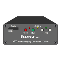
When the On-Line (yellow) light is not lit, the VXM is in the Local/Jog mode. Using the
front panel jog buttons, each motor can be jogged a single step or slewed to 2000 sps (5
revs/sec.) in either direction.
Refer to the “setj” and “setJ” commands in Appendix H for more information about
setting jog speeds to different values.
When a Jog button is pressed the motor moves 1 step (1/400 rev.) If the button is held
for >0.3 second the motor will accelerate to 2000 sps . Pressing Stop while using the
Jog buttons will hold the speed at 39 sps.
Pin# Name Function
1
2
3
4
5
6
7
8
9
10
11
12
13
14
15
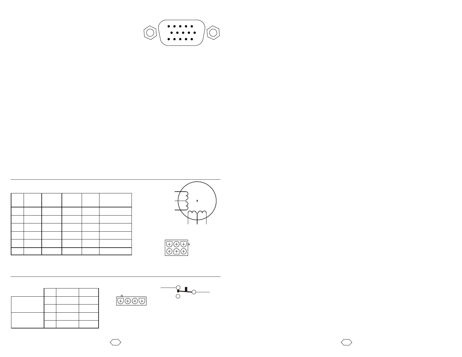
Pin Motor Cable
(6 wire)
Slo-Syn Vexta Pacific
Scientific*
1 BC W W W W/Y & W/R
2 B2 Gn Gn Bu R
3 AC Bk Bk Y W/Bk & W/O
4 A2 Or W/R Bk O
5 A1 R R Gn Bk
6 B1 Bu W/Gn R Y
Motor Wiring (for Velmex installed step motors)
* 8 lead motor with wires combined at AC and BC
for 6 lead configuration
A1
AC
A2
B1 BC B2
Step Motor
1
2
3
4
56
Amp 1-480705-0
(mates with: 1-480704-0 on Cable)
Connector
on Motor
7
6
Limit Switch Wiring
4 3
2
1
Amp 1-480703-0 (mates with: 1-480702-0)
* Negative direction on VXM controllers
Connector on
Switch Harness
Switches are wired on the normally closed (NC) terminals.
CAUTION: The VXM puts 24VDC on the limit switches,
do not connect limit inputs to any +5V logic devices
C
NC
NO
Setup
Auxiliary I/O Connection
Jog Mode
Optional Joysticks
There are two types of external joysticks available for the VXM. One is digital that
functions like the front panel jog buttons, and the second is an analog proportional speed
type that can operate up to 4 motors with 2 VXMs For more information/configuration
refer to Appendix H and J.
I/O
1
2
3
45
1112
1314
15
10
9 8
7
6
The I/O connections can be used for signaling external
equipment or waiting for an external signal. The front
panel button inputs are also available on the I/O
connector for remote jog, run, and stop.
0V
+5V
Ain
Run
I1
I2
I3
I4
0V
J1-
J1+
J2-
J2+
O1
O2
Logic reference ground for inputs and outputs
+5VDC for Joystick power and other external logic (75mA max. output)
Analog input for Joystick, speed setting, or analog sensor.
Run input to start program, same input as Run button (active low)
Input 1 (active low)
Input 2 (active low)
Input 3 (active low)
Input 4 and Stop (Same as Stop button on front panel) (active low)
Logic reference ground for inputs and outputs
Jog Motor 1 CCW (Same as front panel button) (active low)
Jog Motor 1 CW (Same as front panel button) (active low)
Jog Motor 2 CCW (Same as front panel button) (active low)
Jog Motor 2 CW (Same as front panel button) (active low)
Output 1 (normally low)
Output 2 (normally low)
NOTE: All inputs and outputs are TTL levels (0 to +5VDC.) Inputs have resistive
pull-ups, and are activated by connecting to 0V. Outputs are normally low, and can
sink and source 20 mA max. .For more information refer to Appendix K
15DSUBHD Socket
1. Connect the cables to motors and limit switches (if actuator has limit switches.)
Connect the 9 pin serial cable from the VXM’s rear panel connector labeled "RS-232" and
your computer's serial port (usually labeled “COM” or “|O|O|”.) For computers with only
USB ports, use a USB to RS-232 adapter.
CAUTION: Motor cables should never be bundled together with the Limit Switch, or any
I/O cabling. Never put any of the VXM's cables with power cables in a common electrical
conduit or ducting. Always keep Limit Switch and I/O cables at least 2 inches from Motor
and Power cables.
CAUTION: Motor cable length or connectors should not be altered without consulting
Velmex first. Improper wiring can result in poor performance and damage to the VXM.
Altered cables and resultant damage is not covered by the warranty.
IMPORTANT: The VXM can automatically detect limit switch inputs that are wired
normally closed to operate (motor stops on open circuit.) Normally closed is the standard
used on all Velmex products. However, Velmex rotary tables with the home switch option
requires that the limit switch inputs be reconfigured in setup. Refer to the “setL”
command in Extended Version User’s Manual on the CDROM for more information.
CAUTION: Never connect or disconnect motors with the power on, this can result in
severe damage to motor drive electronics.
2. Connect cable from DC power supply to VXM
3. Plug the DC power supply into a AC outlet.
4. Turn on the VXM by pushing the right side of the rocker switch located on the front
panel.
5. Initially the VXM is set for no motors selected (very low power, motors buzz but will
not move.) Use the COSMOS software included on the CDROM to set VXM for the
proper motors. If your computer is not a Windows based system, refer to the “setM”
command in the reference section of this manual.
Both On-Line and Power LEDs will light for 1 second, the On-Line will go out,
then the Power LED will flash 6 times.