I/O Electrical Specifications
Appendix K
61
60
All User I/O inputs and outputs are TTL levels (0 to +5VDC.)
Inputs have a 2200 ohm resistor to +5VDC, and are activated by connecting to 0V.
NOTE: When Input 4 (Stop) is held low (0V) program will not run.*
Outputs are normally low, and can sink and source 20 mA max.
Limit switch inputs are optically isolated. Limit inputs operate on 24VDC through a 10K
ohm resistor to power the LED in the optical isolator (see Appendix N.)
The +5VDC on I/O,2 is intended for use with additional analog input circuitry. Current
draw should not exceed 75mA.
CAUTION:
Optically isolated relays should be used on all user I/Os to insure long term reliable
operation.
Never directly connect a VXM I/O to an inductive load, any device that is not within 10 feet
of the VXM, or anything not powered at the same AC source.
Damage due to improperly interfacing VXM controllers to other devices is not covered
under the warranty.
As a minimum precaution against electrostatic discharge (ESD) damage follow these
guidelines:
1. Provide the shortest conductive path possible to earth ground from user
designed panels or enclosures that have switches or buttons the operator will
come in contact with.
2. Use metal panels and enclosures to house buttons or switches electrically
bonded to a protective earth ground.
3. Use shielded cables on all VXM I/O.
4. If no other protective earth ground is available, use the earth ground on the
VXMs Auxiliary I/O connector shell or connector shell on shielded cable.
* New feature: Only on VXM firmware versions 1.21 & up
See Also
Auxiliary I/O Connection (page 6)
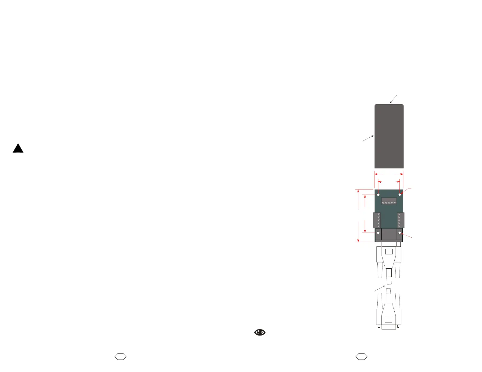
Optional Auxiliary I/O Breakout Module
The optional auxiliary I/O breakout module is a convenient method to interface to the
VXMs auxiliary I/O. Wire connections can be made to all 15 I/O connections using the
screw type terminal blocks.
Specifications
Wire size: 26 to18 AWG
Boot material: PVC
Boot dielectric strength: 700 V/mil
.
4
"
0 9
8
1.738"
2.40"
1.
0"
3
.0
Ø
0
12
"
1 V)(0
2 V)
(+5
3
(Ai
)
n
5
6
7
8
9
1
0
11
1
5
1
4
1
3
1
2
4
Cable with
all 15 through
Protective
Boot
Wire Access Hole
Optional (2)
Pin# Name
1
2
3
4
5
6
7
8
9
10
11
12
13
14
15
0V
+5V
Ain
Run
I1
I2
I3
I4
0V
J1-
J1+
J2-
J2+
O1
O2
!