Limit Switches and Home Switches
Appendix N
69
68
The VXM by default recognizes normally closed (N/C to run) limit switches. The default
mode is auto-detect normally closed switches. If the VXM is used with normally open or
with a home switch, the limit switch mode will need to be changed. The following
command sets the operating mode of the limit switch inputs.
setLmMx Set Limit Switch mode for axis m= motor# (1,2,3,4)
*NOTE: To improve limit switch fault detection set x to 1.
NOTE: Rotary tables with home switches would normally require x =-2.
getLmM Get Limit Switch mode setting for axis m= motor# (1,2,3,4)
m,
x
0= Auto-detect N/C to run (default)*
1= Enabled N/C to run
2= Disabled N/C for Home Switch use
-1= Enabled N/O to run
-2= Disabled N/O for Home Switch use
m, value
returned is either -2,-1,0,1,2 (default=0)
See Also
Limit Switch Wiring (page 6)
Magnetic Reed Switch Wiring
(Activated in both directions)
It is important to understand how a home switch works, and what programming procedure
to use to get a high degree of precision and accuracy obtainable by these switches.
Repeatability of 1 motor step is achievable if the proper procedures are followed when
referencing to a home switch.
The most common home switch used on rotary tables is a magnetic reed type sensor.
The magnetic sensor is usually connected directly to the positive and negative limit switch
inputs on the VXM.
Home switches have an active area of several degrees. Because of this large area where
the switch is activated, it is important to always approach the switch from the same
direction when homing.
Procedure to configure the VXM for use with a home switch:
(For rotary tables only, see page 27 & 46 for linear actuator homing example)
1. Determine which axis (axes) will be connected to a home switch and connect motor,
limit cables, and set VXM for motor type/model attached.
2. Set limit switch function to a value of -2. Example to set motor 1 for use with a
normally open home switch:
Programming sequence for homing to the switch:
(For rotary tables only, see page 27 & 46 for linear actuator homing example)
1. Set a speed for homing (maximum of 1000.) Always use this selected speed for
homing to maintain repeatability.
2. Set move to limit command ( Pick a direction to move to the home
switch. Always use this direction to maintain accuracy. NOTE: if the table is already in
the active area of the switch the table will not move. Steps 3 and 4 below will compensate
for this situation.
4. Set move to limit command (
This example homes motor 1 moving negative direction into home switch and zeroes
position:
setL1M-2<cr>
3. Run the “rsm” command to permanently save limit setting(s)
ImM0, or ImM-0)
3. Set an Index to move back from home switch area to insure table will be totally out of
activated area of the switch before doing final homing. Indexing 4000 steps should be
adequate to move beyond the active switch area.
ImM0, or ImM-0) and zero motor position at this position if
desired.
C S1M600,I1M-0,I1M4000,I1M-0,IA1M-0,R C S1M600,I1M-0,I1M4000,I1M-0,IA1M-0,R
Sensor
Magnet
A
ct
iv
ate
d
A
a
(2
0E
B48
00 Rot ry
r
e
a
30E
B59
90 R
o
t
a
r
y)
Rotary
Table
This example homes motor 2 moving positive direction into home switch and zeroes
position 1000 steps away from switch:
C S2M800,I2M0,I2M-4000,I2M0,I2M-1000,IA2M-0,R C S2M800,I2M0,I2M-4000,I2M0,I2M-1000,IA2M-0,R
1
2
3
4
Sensor
Magnet
Limit Connector
Amp 1-480703-0
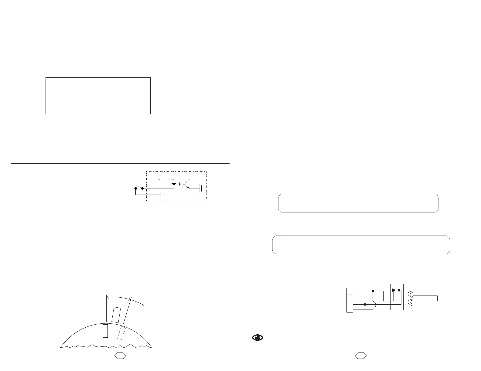
Using Home Switch on Rotary Tables
Limit switch inputs are optically
isolated, from the main control logic of
the VXM, as shown in the diagram at
the right.
VXM
+24V
10K
External
Limit
To MCU
2x per motor