Unit Conversion for Velmex Positioners
* Typical UniSlide model (where x is from above table): MB4024xJ-S4
** Typical BiSlide model (where x is from above table): MN10-0100-x-21
To convert from "real" units to steps, divide the distance desired to move by the
Advance per step. (Distance ÷ Adv per step = Steps)
Example #1: To move 3.000 inches with the BiSlide E04 lead screw (3.000 ÷ 0.001 = 3,000) requires a 3,000 step
index.
Example #2: To move 90 degrees with the B5990 rotary table (90 ÷ 0.01 = 9,000) requires a 9,000 step index.
Example #3: To move 4.000 inches with the UniSlide W1 lead screw (4.000 ÷ 0.00025 = 16,000) requires a 16,000
step index.
Other formulas:
1 Motor rev = 400 steps
Linear Speed = Advance per step x steps per second
Rotary Speed = Advance per step x steps per second
Steps per second ÷ 400 = rev/sec
Lead Screw Models Speed
UniSlide* BiSlide** Advance per turn Advance per step @ 1000 SPS (2.5 rev/sec)
Units Units Units
C P40 0.025 inch 0.0000625 inch 0.0625 inch/sec
B P20 0.05 inch 0.0001250 inch 0.125 inch/sec
W1 P10 E01 0.1 inch 0.0002500 inch 0.25 inch/sec
W2 P5 0.2 inch 0.0005000 inch 0.5 inch/sec
W4 P2.5 E04 0.4 inch 0.0010000 inch 1 inch/sec
K1 Q1 1 mm 0.0025 mm 2.5 mm/sec
K2 Q2 M02 2 mm 0.0050 mm 5 mm/sec
Rotary Tables
Gear Ratio
B4872 72:1 5 degree 0.0125 degree 12.5 degree/sec
B4836 36:1 10 degree 0.0250 degree 25 degree/sec
B4818 18:1 20 degree 0.0500 degree 50 degree/sec
B5990 90:1 4 degree 0.0100 degree 10 degree/sec
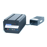
Two controls linked together by the VXM bus make it possible to run 3 or 4 motors with
all programs residing in one VXM, and all communication from a host with this one VXM.
2
The VXM bus is a serial bus conforming to the I C specification. This bus is used to
transfer data back and forth between two VXM controls that are configured as Master
and Slave.
Considerations when linking VXM controls together:
· Use only a Velmex approved cable for the bus connection, telephone handset cables
will not work. Telephone cables reverse the 1 and 4 connection, a straight through cable
is required.
· Bus cables should be short and not be near other cables or electronic devices.
· By default all VXMs are Slaves.
· To link VXMs, one control should be set to be a Master (see Control Mode command
"setDM" in the Appendix O.) The Velmex COSMOS program will configure the VXMs
for Master/Slave operation.
· A designated Master will attempt to establish communications to a Slave on power-up.
If the Master can not find the Slave it will try again when it is required to send a motor 3
or 4 command. NOTE: It is normal for the Slave not to flash its power light (green LED)
at power-up.
· A bus error will occur (” B” sent to host and VXM resets) if the Master can not find the
Slave, either because there is not one connected, or it is not powered.
· The Master is the VXM that runs motors 1 and 2, communicates with a host, and can
be started with the Run input and stopped with the Stop input (Input 4.)
· The Slave runs motors 3 and 4 (The Master assigns motors 3 and 4 to motors 1 and 2
on the Slave) and receives all commands over the VXM bus from the Master.
· The Master disables the Run, Stop, and RS-232 inputs on the Slave.
Ë
Linking VXMs for 3 & 4 Motors (VXM-3,4)
11
10
+
+
+
+
Stepping Motor ControllerStepping Motor ControllerVXMVXM
www.velmex.comwww.velmex.com
VXM
Bus
VXM
Bus
StopStop
RunRun
On-LineOn-Line
LocalLocal
-- --
++ ++
Jog 1Jog 1
Jog 2Jog 2
+
+
+
+
Stepping Motor ControllerStepping Motor ControllerVXMVXM
www.velmex.comwww.velmex.com
VXM
Bus
VXM
Bus
StopStop
RunRun
On-LineOn-Line
LocalLocal
-- --
++ ++
Jog 1Jog 1
Jog 2Jog 2
M2
M4
M1
M3
L1
L3
L2
L4
Master Slave
VXM Bus Cable
Part # 4-2122
C I3M400,R C I3M400,R
Index Motor 3 Example
The VXM uses step units for Index and Speed parameters. One step is 1/400 of a motor
revolution. Step units for distance are used with the Index commands (”I” command.)
Speed is in units of Steps/ Second (SPS.) Steps/ Second units for speed are used with
the Speed commands (”S” command.)
Acceleration commands (”A” command) are values from 1 to 127 that are relative to
2
steps/sec units. The VXM uses a nonlinear acceleration profile, therefore it does not
2
correlate directly to a constant steps/sec .
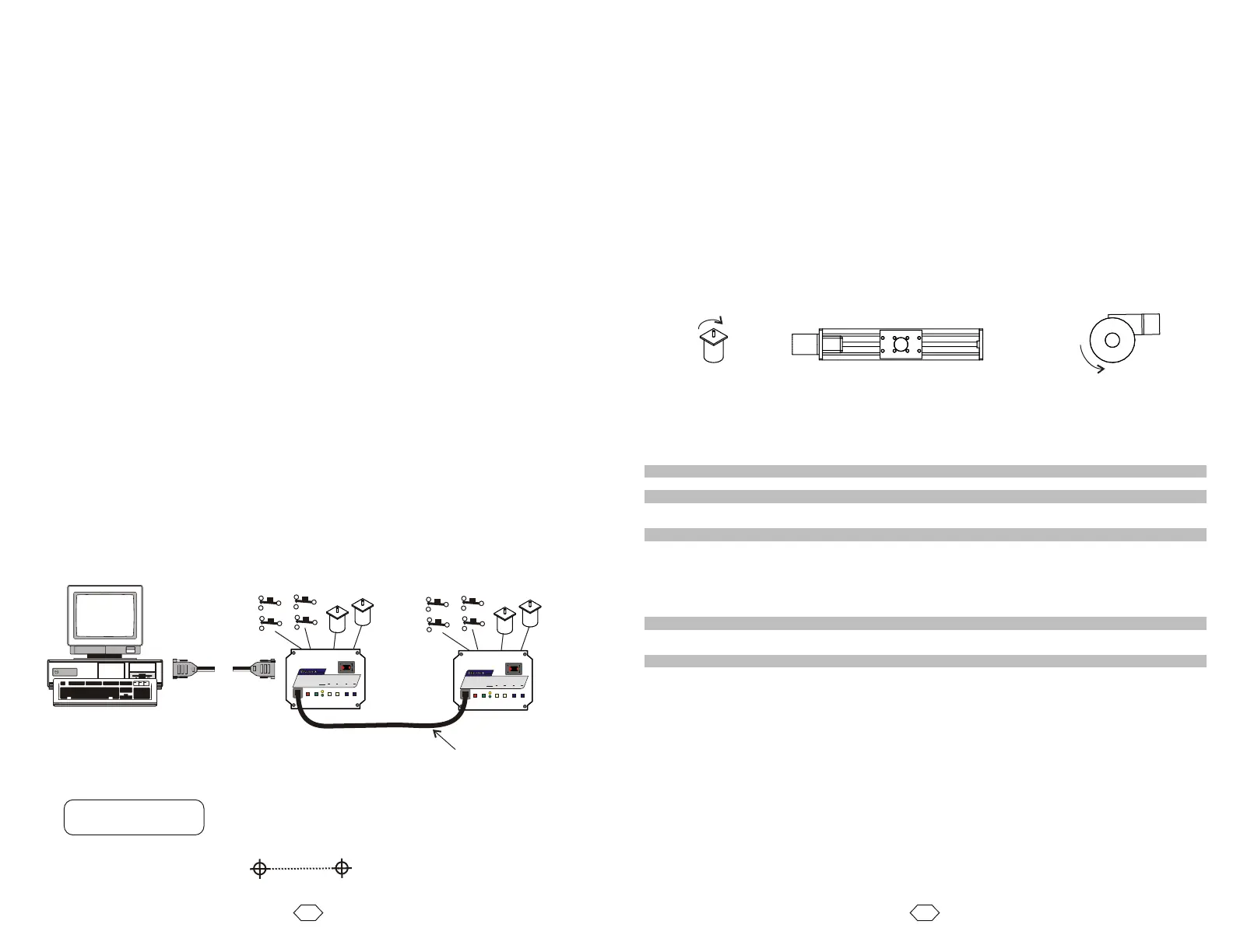
Direction is relative to the device the motor is used on. On screw drive actuators like
UniSlides and BiSlides, positive is the direction moving away from the motor.
On worm gear type rotary tables like the Velmex B4800 or B5990, positive is counter
clockwise (CCW.) To reorient directions refer to the “setDM” command in Appendix O.
Units & Directions
Positive ®
Positive
CCW
Positive
CW
Graphic Representation: ®
start end
¬Clear previous entries, Index Motor 3 +400 steps
Worm Gear
Rotary Table
Screw Drive Actuator
Motor
NOTE: Slave RS-232 port is not used