13
For the Installer
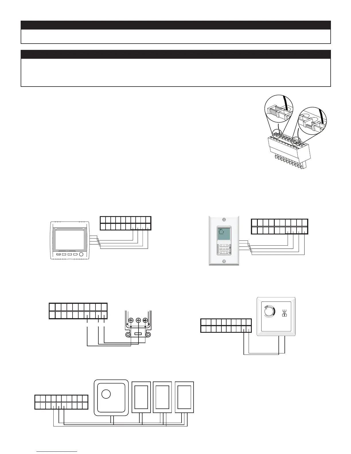
•
• Use the terminal connector included in the installation kit to perform the electrical connection for main
and optional wall controls.
• Make sure all wires are correctly inserted in their corresponding holes in the terminal block. A wire is
correctly inserted when its orange receptacle is lower than another one without wire. On the picture
below, wire A is correctly inserted, but wire B is not.
• Once the connections have been made, insert the terminal connector in the recessed side of the
electrical compartment.
VE0272
A
B
⚠WARNING
Always disconnect the unit before making any connections. Failure in disconnecting power could result in electrical
shock or damage of the wall control or electronic module inside the unit.
CAUTION
Never install more than one optional main wall control per unit. Make sure that the wires do not short-circuit
between themselves or by touching any other components on the wall control. Avoid poor wiring connections. To
reduce electrical interference (noise) potential, do not run wall control wiring next to control contactors or near
light dimming circuits, electrical motors, dwelling/building power or lighting wiring, or power distribution panel.
NO C NC I OC OL Y R G B
VE0181
SMART
SET
MODE
PREF
NO C NC I OC OL Y R G B
VE0250
7.3.1 ALTITUDE OR PLATINUM 7.3.2 DECO-TOUCH
7.3.3 LITE-TOUCH CONSTRUCTO OR LITE-TOUCH BRONZE 7.3.4 CONSTRUCTO OR BRONZE
NO C NC I OC OL Y R G B
BG
G
B
Y
VE0328A
Y
7.3.5 OPTIONAL AUXILIARY CONTROLS
NO C NC I OC OL Y R G B
VE0323
--5°C
23°F
5
°
C
41
°
F
C
O
M
F
O
R
T
Z
O
N
E
-20°C
-4°F
OFF
MIN MAX
#
X
X
X
X
X
0
1
/
9
8
NO C NC I OC OL Y R G B
20/40/60-MINUTE or 20-MINUTE
PUSH-BUTTON SWITCHES
(5 MAXIMUM)
60-MINUTE
CRANK TIMER
VE0089A
DEHUMIDISTAT
 Loading...