7
For the Installer
5. TECHNICAL DATA
5.1 AIR DISTRIBUTION
NORMAL OPERATION DEFROST OR RECIRCULATION
VF0045
VF0046
STALE AIR
TO OUTDOORS
FRESH AIR
FROM OUTDOORS
STALE AIR
FROM
BUILDING
FRESH AIR
TO
BUILDING
STALE AIR
FROM
BUILDING
FILTERED AIR
TO
BUILDING
6. INSTALLATION
6.1 DOOR CONFIGURATION
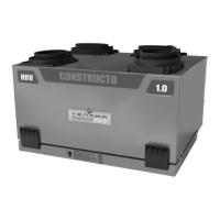
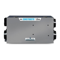
E15 ECM ERV These units are equipped with one front door and one back door.
E15 ECM HRV
90H-V ECM ERV
90H-V ECM HRV
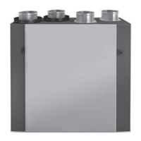
E15 HRV These units have one door. In order to optimize duct configuration while maintaining access for maintenance, the
door can be switched sides:
• Remove the door:
- Remove both screws holding the bottom of the door and set aside.
- Open and lift the door to remove it.
• Remove the back panel:
- Remove the 4 screws holding the back panel, and set aside.
• Hang the door to the back of the unit and secure using both screws previously removed.
• Install the back panel to the front of the unit using the 4 screws previously removed.
E10 HRV
90H-V+
60H-V+
6.2 LOCATING THE UNIT
Choose an appropriate location for the unit:
• Within an area of the house where the ambient temperature is kept between 10°C
(50°F) and 40°C (104°F)
• Away from living areas (dining room, living room, bedroom), if possible
• So as to provide easy access to the interior cabinet for quarterly and annual
maintenance, and to the control panel
• Close to an exterior wall, so as to limit the length of the insulated flexible duct to and
from the unit
• Close to a drain. If no drain is close by, use a pail to collect run-off
• Away from hot chimneys, electrical panel and other fire hazards
• Allow for a power source (standard outlet)
Hang the unit with the 4 chains and springs provided (see illustrations at right).
VD0205
CAUTION
Make sure that the unit is level.
CAUTION
Before installing this unit, please take the time to carefully read page 2 of this guide to ensure it is installed safely
and properly.
 Loading...