16
Rev. 01.01
INSTALLATION
4. INSTALLATION
4.3 ELECTRICAL INSTALLATION
ATTENTION!
• Before beginning repair or modication of
the HRV unit, make sure the main power
switch is off!
• The wiring must be done by a person authorized
to perform electrical installations. It is neces-
sary to follow all instructions in this manual and
to comply with local laws and regulations.
• Before connecting the wiring, make sure that
terminal indications match the diagram. If in
doubt, do not connect the unit, and contact the
supplier!
• The unit must be connected to the mains using
a heat-protected, insulated cable with a cross-
section that meets local regulations.
• To maintain electrical protection, all cables must
t in the hole on the sides of the control unit
casing (1/2" ex-conduit connector).
• Any changes or modications to the internal
wiring of the unit are prohibited and will void
the warranty!
• The unit’s correct operation can be guaranteed
only if original accessories are used.
• If it is necessary to install a sensor or control
component in the unit or on its casing, consult
beforehand with the unit manufacturer or rep-
resentative.
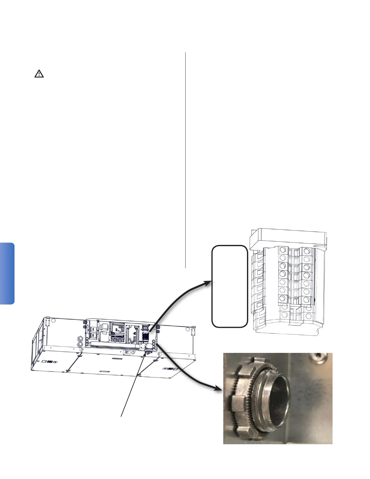
4.3.1 SUPPLY WIRING
Adjacent to the main power switch is a 7/8" hole
through the regulator box and a pre-installed 1/2"
ex-conduit connector. If the electrical installer
decides, the pre-installed connector can be re-
moved and supplanted with an appropriate tting
rated for:
• The listed Maximum Overcurrent Protection of
the device.
• The listed voltage of the device.
• 3 10AWG insulated wires: Line 1,
Line 2 (Neutral), and Protective Earth Ground.
• Compliance with local laws and regulations.
Route the power wires in an appropriate conduit
from the service to the unit. Fix the conduit the
the regulator box power wire entry connector.
Terminate the power supply wires to the terminal
blocks labeled:
"MAIN POWER SUPPLY"
Wire the mains (PE, L1, L2) to the appropriate ter-
minal block (PE, L, N).
MAIN POWER
SUPPLY
Power Switch
Terminal Blocks
Conduit Connector
PE
N
L