17
Rev. 01.01
INSTALLATION
4. INSTALLATION
Accessories ordered separately
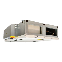
4.4 DAMPER MODULE INSTALL
These rectangular air aps are used to close the
air supply connected to the unit. See Specica-
tions section for duct connection dimensions.
●2rectangularaps(ofsuitabledimensions)
●2actuators*(withoneortwo230Vwires)
●8M8screwsandnuts
●16washers
●suitablewrench
●Flat and Phillips screwdriver, sealing tape and
sealant
*IncludedwithVentacitysupplieddampermodule
YOU WILL NEED
Install the ap in the ductwork at a distance of
about 7 feet before the fresh air intake and at
about 7 feet from the exhaust neck. Connect the
actuators to the appropriate terminals in the con-
trol cabinet. See Connecting the wiring and elec-
trical accessories
Place the ap so it will be fully closed when the
unit is off and fully open when the unit is on. Any
other position could damage the unit.
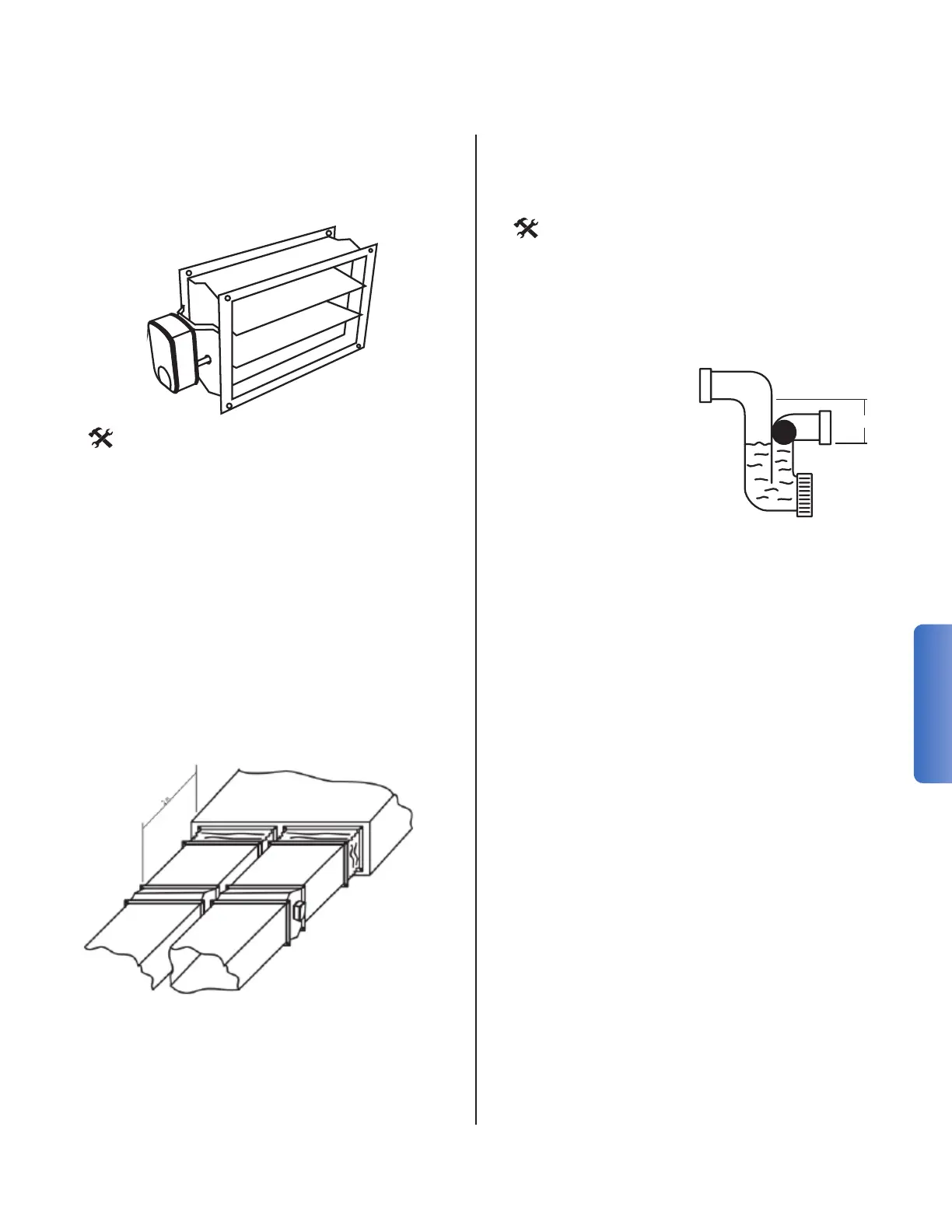
4.5 CONDENSATE DRAIN INSTALL
It is recommended to connect the condensate
drain to the drainage piping. The siphon has built-
in antifreeze protection.
YOU WILL NEED
• 1 siphon
• PVC drainage pipes
• sealing for the drainage piping
h2 h1
h
1
Siphon courant Ball Siphon
The tank’s neck is located on the
side/sides of the unit.
Attach to it the siphon or to a hose
connected to the drainage.
- Make sure that the unit is tilted 3° in order to
drain the condensate.
5.12"