38
Rev. 01.01
REFERENCE
6. REFERENCE
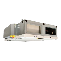
Location of fuses on the "A" control board
READ CAREFULLY!
In case of power failure and subsequent recovery
of the power supply, the unit returns to its state
before the failure. The unit always remembers its
operatingstatusandconguration.
Ifyoufailtondorremovethecauseoftheerror,
or if the repair requires intervention in the unit,
contactanauthorizedserviceprovider.
6.3 SERVICE
6.3.1 If The Error Persists
If you cannot resolve the error, please contact the
supplier.
READ CAREFULLY!
Provide the following information to facilitate cor-
rectingtheerror:
• Product type
• Serial number
• Operatingtime
• Used accessories
• Unit location
• Connection conditions (including electrical
conditions)
• Detailed description of the error and steps
taken to remove it.
6.3.2 Decommissioning and
Product Disposal
Please make sure the unit is inoperative before
disposal. Older units also include reusable materials.
Take them to a waste separation site.
The product should be dismantled in a specialized
center so that the recyclable materials can be
reused. Parts that cannot be recycled should be
taken to a legal waste disposal site.
Materials must be disposed of in accordance with
applicable national regulations and directives.
This product must be disposed of in accordance with
local laws and regulations.
The product contains batteries and therefore it must be
recycled or disposed of separately from household waste.
When the battery or the product reaches the end of its
service life, contact your dealer or local authorities and
ask about recycling options. The separate collection and
recycling of your product and its battery will help to pre-
serve natural resources and ensure that the product will
be recycled in a manner that protects human health and
the environment.
Fuses on the cont board:
T2A 5x20mm 250V
Fuses engine:
information is placed on the label next to
the fuse box, or directly on the fuse
Control panel
1
1.
1
5.
1
6.
1
2.
1
7.
1
8.
1
9.
1
10.
1
11.
1
12.
1
13.
1
14.
1
15.
1
16.
1
17.
1
3.
1
4.
20.
1
18.
1
19.
EN RU CZ
1. A (5-6) LF1 - FLAP INLET (output L-open), LF2 - FLAP OUTLET ( output L-open) LF1 ( L-), LF2 - ( L-) LF1 - KLAPKA PŘÍVOD (výstup L-open), LF2 - KLAPKA ODVOD ( výstup L-open)
2. A (7-8) RUN CONTACT (output -NO/NC settable) RUN ( - NO/NC ) RUN KONTACT (výstup -NO/NC nastavitelné)
3. A (9-10) ERROR CONTACT (output NO) ( NO) ERROR KONTACT (výstup NO)
4. A (11-12) PREHEATER WATER PUMP (11 - Lint, 12 - Lout) (11 - Lint,12 - Lout) VODNÍ ČERPADLO PŘEDEHŘEVU (11 - Lint, 12 - Lout)
5. A (13-14) BOOST (input NO) BOOST ( NO) BOOST (vstup NO)
6. A (15-16) FIRE (input NC) FIRE - ( NC) FIRE (vstup NC)
7. A (17-18) EXTERNAL CONTROL ON/OFF (input NC) ON/OFF ( NC) EXTERNÍ OVLÁDÁNÍ ON/OFF (vstup NC)
8. A (18-19) AQS SENSOR 0-10V (input) 0-10 () ČIDLO KVALITY VZDUCHU 0-10V (vstup)
9. B (1-2) WATER PUMP (1 - Lint, 2 - Lout) (1 - Lint, 2 - Lout) VODNÍ ČERPADLO (1 - Lint, 2 - Lout)
10. B (3-4) HEAT PUMP CONTROL settable (output - ON/OFF) ( - ON/OFF) ŘÍZENÍ TEPELNÉHO ČERPADLA nastavitelné (výstup - ON/OFF)
11. B (5-6) ADIABATIC MODULE output - ON/OFF ( - ON/OFF) ADIABATICKÝ MODUL výstup - ON/OFF
12. B (7-8) COOL / HEAT settable (CO = NC/NO - DX = output settable) / (CO = NC/NO - DX = ) CHLAZENÍ / TOPENÍ nastavitelné (CO = NC/NO - DX = výstup nastavitelné)
13. B (9-10) ADIABATIC MODULE ERROR input NO ERROR ( NO) ADIABATICKÝ MODUL ERROR vstup NO
14. B (11-12) HEAT PUMP DEFROST settable (input NC/NO) ( NC/NO) ODMRAŽOVÁNÍ TEPELNÉHO ČERPADLA nastavitelné (vstup NC/NO)
15. B (13-14) HEAT PUMP ERROR settable (input NC/NO) ( NC/NO) CHYBA TEPELNÉHO ČERPADLA nastavitelné (vstup NC/NO)
16. B (15-16) PIR (input NC) PIR ( NC) POHYBOVÉ ČIDLO PIR (vstup NC)
17. B
(17-18) CONDENSATE OVERFLOW (input NC) ( NC) ČIDLO PŘETEČENÍ KONDENZÁTU (vstup NC)
18. B (46-47) EXTERNAL TEMPERATURE SENSOR (external postheater - input) ( - ) EXTERNÍ TEPLOTNÍ ČIDLO (externí dohřev - vstup)
19. B (44-45) EXTERNAL TEMPERATURE SENSOR (adiabatic module / recirc. chamber - input) ( / - ) EXTERNÍ TEPLOTNÍ ČIDLO (adiabatický modul / recirkulační komora - input)
20. B (38-39) EXTERNAL PREHEATER (output - Water= 0-10V, electric=PWM) ( - =0-10, =PWM) EXTERNÍ PŘEDEHŘEV (výstup - vodní=0-10V, elektrický=PWM)
21 B (36-37) EXTERNAL POSTHEATER (output - Water= 0-10V, electric=PWM) ( - =0-10, =PWM) EXTERNÍ DOHŘEV (výstup - vodní=0-10V, elektrický=PWM)
22 B (34-35) RECIRCULATION CHAMBER (output 0-10V) ( 0-10) RECIRKULAČNÍ KOMORA (výstup 0-10V)
A
B
21.
BROWN
a
 Loading...