23
Rev. 01.01
INSTALLATION
4. INSTALLATION
• Insert the other end of the cable to one of the
connectors on the control computer board.
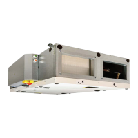
4.8.3 CONTROL PANEL CONNECTION
To activate the unit, it is necessary to connect the
control panel and the unit using the communication
cable (data cable).
• Loosen the screw on the bottom of the con-
trol panel.
• Open the control panel case.
• Connect the control cable conductors as
shown below.
• Attach the user interface panel to the wall.
• Close and tighten the control panel case.
READ CAREFULLY!
●Thesupplyandthecontrolcableshouldbeasfar
apart from each other as possible.
●Make sure that the cable has been properly
connected at screw terminals.
●Becarefulnottodamagecableinsulationwhen
xing the control panel to the wall or to other
surface.
●If you do not connect cables directly during
the unit’s installation, protect them against
mechanical damage or short circuit with
insulating tape.
●Cable connectors must not come into contact
with water or other liquid.
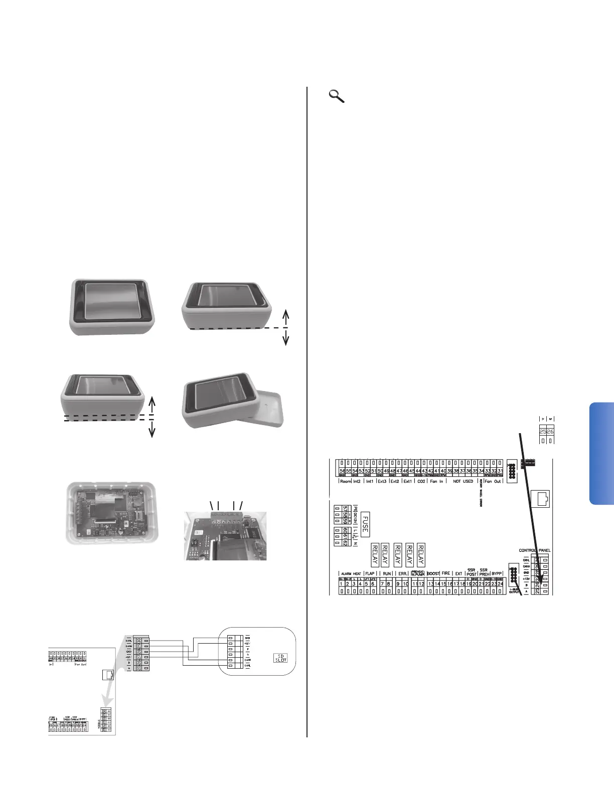
4.8.4 CONNECTING UNIT TO BMS CONTROL
SYSTEM
The HRV unit’s control includes the RS-485
interface. Connect the HRV computer control with
a standard Cat6, RJ45 communication cable. Insert
the cable BMS end into one of the connectors on
the HRV unit’s computer control board. Connect
the other end to the main BMS end computer
control.
1.
3.
5.
2.
4.
6.
CANL (30)
CANH (29)
+12V (27)
GND (28)
Control panel
1
1.
1
5.
1
6.
1
2.
1
7.
1
8.
1
9.
1
10.
1
11.
1
12.
1
13.
1
14.
1
15.
1
16.
1
17.
1
3.
1
4.
20.
1
18.
1
19.
EN RU CZ
1. A (5-6) LF1 - FLAP INLET (output L-open), LF2 - FLAP OUTLET ( output L-open) LF1 ( L-), LF2 - ( L-) LF1 - KLAPKA PŘÍVOD (výstup L-open), LF2 - KLAPKA ODVOD ( výstup L-open)
2. A (7-8) RUN CONTACT (output -NO/NC settable) RUN ( - NO/NC ) RUN KONTACT (výstup -NO/NC nastavitelné)
3. A (9-10) ERROR CONTACT (output NO) ( NO) ERROR KONTACT (výstup NO)
4. A (11-12) PREHEATER WATER PUMP (11 - Lint, 12 - Lout) (11 - Lint,12 - Lout) VODNÍ ČERPADLO PŘEDEHŘEVU (11 - Lint, 12 - Lout)
5. A (13-14) BOOST (input NO) BOOST ( NO) BOOST (vstup NO)
6. A (15-16) FIRE (input NC) FIRE - ( NC) FIRE (vstup NC)
7. A (17-18) EXTERNAL CONTROL ON/OFF (input NC) ON/OFF ( NC) EXTERNÍ OVLÁDÁNÍ ON/OFF (vstup NC)
8. A (18-19) AQS SENSOR 0-10V (input) 0-10 () ČIDLO KVALITY VZDUCHU 0-10V (vstup)
9. B (1-2) WATER PUMP (1 - Lint, 2 - Lout) (1 - Lint, 2 - Lout) VODNÍ ČERPADLO (1 - Lint, 2 - Lout)
10. B (3-4) HEAT PUMP CONTROL settable (output - ON/OFF) ( - ON/OFF) ŘÍZENÍ TEPELNÉHO ČERPADLA nastavitelné (výstup - ON/OFF)
11. B (5-6) ADIABATIC MODULE output - ON/OFF ( - ON/OFF) ADIABATICKÝ MODUL výstup - ON/OFF
12. B (7-8) COOL / HEAT settable (CO = NC/NO - DX = output settable) / (CO = NC/NO - DX = ) CHLAZENÍ / TOPENÍ nastavitelné (CO = NC/NO - DX = výstup nastavitelné)
13. B (9-10) ADIABATIC MODULE ERROR input NO ERROR ( NO) ADIABATICKÝ MODUL ERROR vstup NO
14. B (11-12) HEAT PUMP DEFROST settable (input NC/NO) ( NC/NO) ODMRAŽOVÁNÍ TEPELNÉHO ČERPADLA nastavitelné (vstup NC/NO)
15. B (13-14) HEAT PUMP ERROR settable (input NC/NO) ( NC/NO) CHYBA TEPELNÉHO ČERPADLA nastavitelné (vstup NC/NO)
16. B (15-16) PIR (input NC) PIR ( NC) POHYBOVÉ ČIDLO PIR (vstup NC)
17. B
(17-18) CONDENSATE OVERFLOW (input NC) ( NC) ČIDLO PŘETEČENÍ KONDENZÁTU (vstup NC)
18. B (46-47) EXTERNAL TEMPERATURE SENSOR (external postheater - input) ( - ) EXTERNÍ TEPLOTNÍ ČIDLO (externí dohřev - vstup)
19. B (44-45) EXTERNAL TEMPERATURE SENSOR (adiabatic module / recirc. chamber - input) ( / - ) EXTERNÍ TEPLOTNÍ ČIDLO (adiabatický modul / recirkulační komora - input)
20. B (38-39) EXTERNAL PREHEATER (output - Water= 0-10V, electric=PWM) ( - =0-10, =PWM) EXTERNÍ PŘEDEHŘEV (výstup - vodní=0-10V, elektrický=PWM)
21 B (36-37) EXTERNAL POSTHEATER (output - Water= 0-10V, electric=PWM) ( - =0-10, =PWM) EXTERNÍ DOHŘEV (výstup - vodní=0-10V, elektrický=PWM)
22 B (34-35) RECIRCULATION CHAMBER (output 0-10V) ( 0-10) RECIRKULAČNÍ KOMORA (výstup 0-10V)
A
MODBUS connection
EXT
 Loading...