Do you have a question about the Verkada AC42 and is the answer not in the manual?
Provides version and publication date of the installation guide.
Explains how to verify the firmware version for the product.
Details the product's access control levels and grades.
Lists the performance levels according to UL294 standards.
Specifies the grade assignment according to CAN/ULC-60839-11-1.
Outlines compliance statements for FCC and IC regulations.
Details the FCC compliance rules and potential interference.
Provides the Industry Canada (ISED) compliance statement for license-exempt RSSs.
Specifies the intended use environment for the equipment.
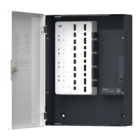
Lists all components included in the AC42 product packaging.
Lists the external tools and resources required for installation.
Guides on connecting the AC42 to network and power, and where to start.
Explains the meaning of different LED states for the controller's status.
Describes the LED indicators for door status, AUX output, and FAI.
Summarizes the primary functions and port types of the AC42 controller.
Guides on using the mounting template and installing the mount plate on the wall.
Instructions on unlocking the enclosure and removing the door for installation.
Steps to slot the enclosure onto the mount plate and secure it to the wall.
Instructions for reattaching the enclosure door and connecting the grounding cable.
Details recommended wire types, AWG, and lengths for reader connections.
Explains the importance and method of using shield wiring and grounding.
Lists the necessary network configuration, including ports and protocols.
Introduces door port relay options (dry/wet) and fail-safe/fail-secure concepts.
Explains the dry configuration where the AC42 does not provide power to the lock.
Describes the wet configuration where the AC42 provides power to the lock.
Defines fail secure and fail safe locking methods and their typical configurations.
Details connecting locks in dry and wet configurations, including voltage settings.
Specific instructions for connecting a lock using an external power supply in dry mode.
Instructions for connecting locks in wet mode, including voltage selection and wiring polarity.
Guides on connecting Verkada/RS-485 and standard Wiegand readers to the AC42.
Explains how to connect readers using shielded cables and chassis ground.
Details connecting Door Position Indicator (DPI) and Request-to-Exit (REX) inputs.
Explains the DPI and REX inputs as dry contacts and their configuration options.
Illustrates wiring REX with door strikes and electromagnetic locks in dry and wet configurations.
Shows how to wire the REX input in parallel with a door strike for safety applications.
Details wiring the REX input directly to an electromagnetic lock.
Covers the configuration and use of the AC42's Auxiliary (AUX) inputs and outputs.
Explains the function of the two AUX inputs and their default/configurable states.
Describes the two AUX Form C relays and their use for triggering outputs during lockdowns.
Details the setup for the Fire Alarm Interface (FAI) using normally closed and open inputs.
Explains wiring a normally closed FACP input to the AC42 FAI terminals.
Explains wiring a normally open FACP input to the AC42 FAI terminals.
Covers latching FAI inputs and daisy-chaining multiple AC42 units for FAI.
Describes how to configure a latching input for the FAI to maintain its state until reset.
Explains how to connect multiple AC42 units in a daisy chain for FAI functionality.
Final steps for connecting the AC42 to the network and adding it to the Verkada Command account.
Instructions for connecting an optional 12V 4.5Ah battery for backup power.
Provides contact information for Verkada's 24/7 Technical Support Team.
| Model | AC42 |
|---|---|
| Category | Controller |
| Power Consumption | 12W max |
| Connectivity | Ethernet |
| Relays | 2 |
| Reader Ports | 2 |
| Power Input | 12V DC |
| Humidity | 0% to 90% (non-condensing) |
| Warranty | 5 years |
| Network Interface | 10/100 Ethernet |
| Supported Devices | Verkada access control devices |
| Certifications | CE, FCC, UL |