User Manual MicroDispensing Systems MDS 3010A-FD and MDS 3020A-FD
User Manual MicroDispensingSystems MDS 3010A-FD and MDS 3020A-FD
VTK-TS-MA-032 Revision D 42
7. Connection/Mounting
7.1. Assembling the valve
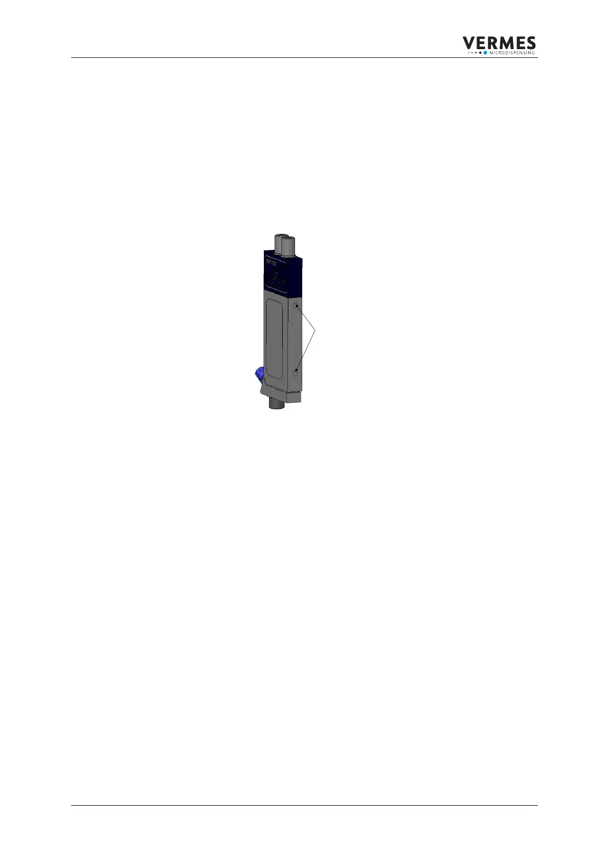
The MicroDispensing Valve should be mounted on a smooth and even vertical space by means of the two
tap holes (M4) at the narrow side. The distance between the tap holes is 45 mm. The screwing depth is
approximately 4 mm. All parts in contact with the MicroDispensing Valve (screws, fixing plates etc.) should
be made of stainless steel, non-ferrous metals or galvanized steel. Contact with non-refined ordinary steel
may cause so-called “external rust”.
Figure 13: Image of the tap of the holes of the valve MDV
7.2. Assembling the control unit
The control unit MDC 3090A-FD is designed as an insert for a 19” plug-in module. It may be fixed in a
place, sufficiently ventilated as well as easy to reach from the rear and the front side in a 19” rack with 4
front side screws. The connecting cables have to be thoroughly guided. All connectors must be fixed tight.
A possible interchanging of plugs and sockets is prevented by corresponding coding.
2x Gewinde M4
Einschraubtiefe jeweils 4 mm
Mittelpunktabstand 45 mm
2x thread M4
Screw-in depth 4mm
Centre distance 45 mm


 To Next Page