User Manual MicroDispensing Systems MDS 3010A-FD and MDS 3020A-FD
User Manual MicroDispensingSystems MDS 3010A-FD and MDS 3020A-FD
VTK-TS-MA-032 Revision D 43
7.3. Electrical connections
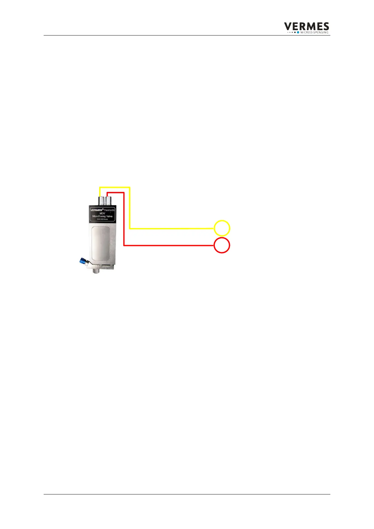
The connection of the MicroDispensing Valve is done via the two sockets on the sensor electronics
module. The sockets are protected against mix-up by a differing number of pins (sensor 5, actuator 4). The
red dots on the socket and the plug must point to each other when connecting. The cable marked with a
red tension relief supplies the power for the piezo stack from 0 V to 200 V. Via the second cable (yellow
tension relief) the data of the tappet sensor integrated in the MDV 3xxx is transferred. Disconnection is
done by pulling the riffled bush axially backwards.
Step 1: Make sure the power cable is disconnected from the control unit.
Step 2: Connect both control cables (red and yellow tension relief) to the MicroDispensing Valve. Pay
attention to the coding of the cable and females.
Step 3: Connect both control cables to the back side of the control unit (screw tightly!).
Step 4: Connect the power cable to the back side of control unit. Before connecting pay attention to line
switch „0“-position, i.e. when the inscription „0“ is visible (top view).
Figure 14: Connection scheme of valve and control unit


 To Next Page